
Method of assigning elevators for sky lobbies

a technology of elevators and sky lobbies, applied in the direction of elevators, transportation and packaging, etc., can solve the problems of increasing the time it takes for passengers to reach the higher floors, affecting the service level, and increasing the time for passengers to complete the shuttle elevator trip, so as to reduce the average round trip time of all elevators and improve the service level. , the effect of reducing the round trip tim

Active Publication Date: 2006-10-03
OTIS ELEVATOR CO
View PDF4 Cites 3 Cited by
  • Summary
  • Abstract
  • Description
  • Claims
  • Application Information

AI Technical Summary

Benefits of technology

[0041]The round trip time is reduced for each elevator. The average round trip time for all of the elevators is significantly reduced. As a result, the service level is improved. Because the round trip time of the elevator is reduced, the departure interval becomes shorter, the transporting ability (such as the 5-min transporting ability) is increased, and the average transporting ability of all of the elevators is increased significantly. Consequently, the number of elevator cars required can be significantly reduced.
[0042]The aforementioned effects are not limited to single-deck elevators. The same effects can be also be realized for the double-deck elevator. In addition, the aforementioned effects become more significant as the building becomes higher. For example, the effect is excellent when this invention is adopted in an elevator system that has plural sky lobbies with express operation being performed between the building lobby and the sky lobbies.

Problems solved by technology

However, when several sky lobbies are provided (for example, when a sky lobby is provided for every 150 m in a building 750 m high), when conventional elevator operation is used, the time for the shuttle elevator to complete a trip becomes much longer, and the service level becomes much poorer.
On the other hand, because passengers going to lower floors and passengers going to higher floors share the same elevator, the time it takes for passengers to reach higher floors becomes longer, especially during the rush hour, and a longer time is needed for the elevator to return to the lobby (the ground floor building lobby).
As a result, more passengers have to wait, and the lobby becomes crowded.
This is undesirable.
On the other hand, however, when there are many passengers in a certain group, the lobby becomes crowded, while the elevators for other groups are idled.
This is undesirable.
This is also undesirable.
However, because the number of sectors and the number of floors are fixed in the channeling (static channeling) shown in FIGS. 8–10, if a large number of passengers wants to travel to a certain floor at the same time, the riding time for the sector containing said floor becomes longer, and the overall service level for the entire sector may degrade.
Consequently, the round trip time from departure to return to the starting floor after serving multiple floors is long.
Consequently, the round trip time becomes longer.
This problem becomes more significant when the building becomes higher and the number of floors is increased.
However, when more than one sky lobby is provided, just as with a conventional elevator, sequential stop service is provided, and, finally, the criteria pertaining to the predicted number of stops (running cycle number[sic], door opening / closing time, time for passengers getting on and off, loss time) are added to the round trip time, so that the round trip time becomes much longer.

Method used


Image

  • Method of assigning elevators for sky lobbies
  • Method of assigning elevators for sky lobbies
  • Method of assigning elevators for sky lobbies

Examples


Embodiment Construction

[0056]Embodiments of this invention will be described in the following, illustrated by figures.

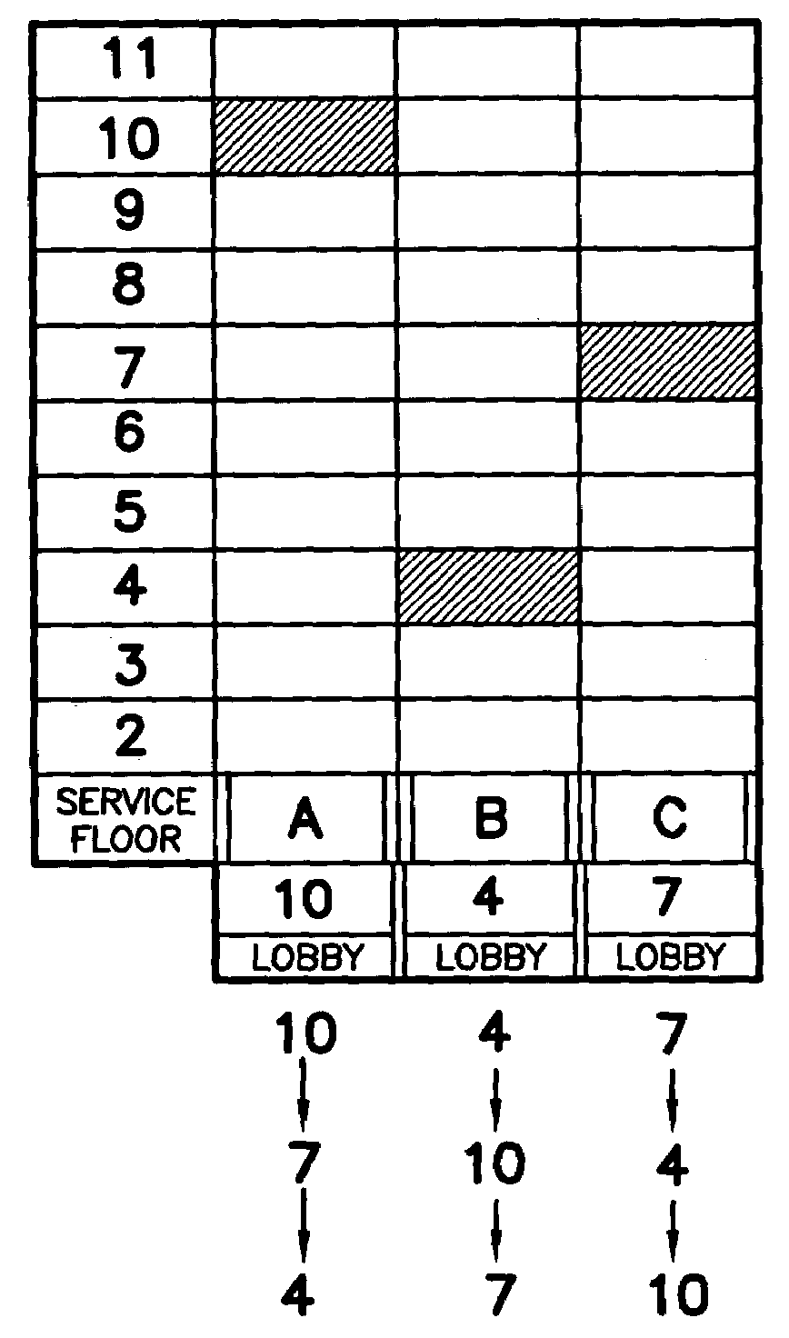
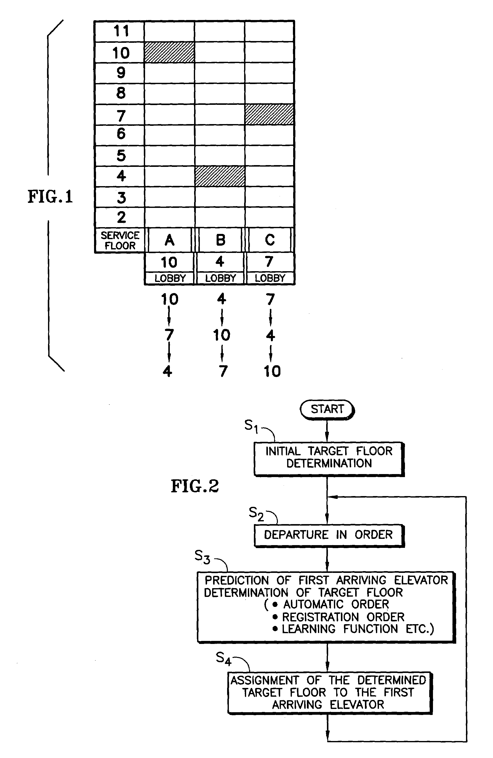
[0057]FIG. 1 is a diagram illustrating the principle of operation when this invention is adopted in a conventional elevator. FIG. 2 is a flow chart illustrating processing performed by the computer of the operation system in this invention.

[0058]According to this invention, first of all, plural elevator units A-C are each assigned to a unique service floor that is different from the others (step S1). As indicated by the hatched portions in FIG. 1, the 10th floor is assigned as the target floor for first-departing unit A; the 4th floor is assigned as the target floor for the next-departing unit B; and the 7th floor is assigned as the target floor for the last-departing unit C.

[0059]Then, an operation mechanism not shown in the figure drives the elevators sequentially to the respective service floors (step S2).

[0060]Then, in step S3, the computer in the operation system predicts which elevat...


PUM


Abstract

An elevator operation system and apparatus reduce the round trip time of an elevator, by determining a target floor that corresponds to the destination floor requested by a passenger; and assigning the target floor to one of a plurality of elevators for service exclusively to the target floor.

Description

FIELD OF THE INVENTION[0001]This invention pertains to a type of elevator system that can move up / down along an elevator shaft in a building. More specifically, this invention pertains to an elevator operating system and elevator operation method characterized by the fact that it can improve the operation efficiency of the dedicated shuttle elevators for the sky lobbies in an ultrahigh building.BACKGROUND OF THE INVENTION[0002]Usually, as buildings become higher, the space occupied by elevators becomes greater, and the usable space in the building becomes smaller. For example, in Landmark Tower in Yokohama, Japan, about ⅓ the total space is occupied by elevators.[0003]As a means for improving the efficiency of elevators in ultrahigh buildings, the sky lobby system has been proposed. In this system, a sky lobby is provided as a transit lobby on a floor at nearly the midpoint of the total height of the building. A shuttle elevator is provided that is dedicated (goes directly) to the s...

Claims


Application Information

Patent Timeline
Patent Type & Authority Patents(United States)
IPC IPC(8): B66B1/18B66B1/20B66B1/24
CPCB66B1/2458B66B2201/103B66B2201/211B66B2201/214B66B2201/215B66B2201/225B66B2201/301B66B2201/303B66B2201/305
Inventor URATA, MASAZUMI
Owner OTIS ELEVATOR CO
Learn More