
Medical device having releasable retainer

a technology of a retainer and a medical device, which is applied in the field of medical devices, can solve the problems of blood or other fluids being lost, inadvertent disconnection of the needle assembly, and potential contamination

Inactive Publication Date: 2006-10-03
BECTON DICKINSON & CO
View PDF43 Cites 31 Cited by
  • Summary
  • Abstract
  • Description
  • Claims
  • Application Information

AI Technical Summary

Benefits of technology

[0011]Still another alternative embodiment of the needle assembly of the present invention further includes a needle guard having a proximal end, a distal end and a needle passageway therethrough. The needle guard is movable along the needle cannula from a first position substantially adjacent the proximal end of the needle cannula to a second position where a distal tip of the needle cannula is intermediate the opposed proximal and distal ends of the needle guard. A hinged arm having proximal and distal segments articulated to one another for movement between a first position wherein the segments are substantially collapsed onto one another and a second position where the segments are extended from one another is provided. The proximal segment of the hinged arm is articulated to a portion of the hub. The distal segment of the hinged arm is articulated to the needle guard. The proximal and distal segments of the hinged arm have respective lengths for permitting the guard to move from the first position to the second position on the needle cannula and for preventing the guard from moving distally beyond the second position. The components of the hinged arm may be integrally molded of thermoplastic material.

Problems solved by technology

If the syringe tip becomes disengaged from the needle assembly, medication, blood or other fluids will be lost, and there is also potential for contamination.
Many of the structures taught by the prior art do not contemplate the subsequent removal of the needle assembly from the syringe barrel.
Difficulties can arise if the user does not use enough force to frictionally engage the luer tapered surfaces which can result in inadvertent disconnection of the needle assembly.

Method used


Image

  • Medical device having releasable retainer
  • Medical device having releasable retainer
  • Medical device having releasable retainer

Examples


Embodiment Construction

[0029]While this invention is satisfied by embodiments in many different forms, there are shown in the drawings and will herein be described in detail, preferred embodiments of the invention with the understanding that the present disclosure is to be considered exemplary of the principles of the invention and not intended to limit the invention to the embodiments illustrated. The scope of the invention will be measured by the appended claims and their equivalents.

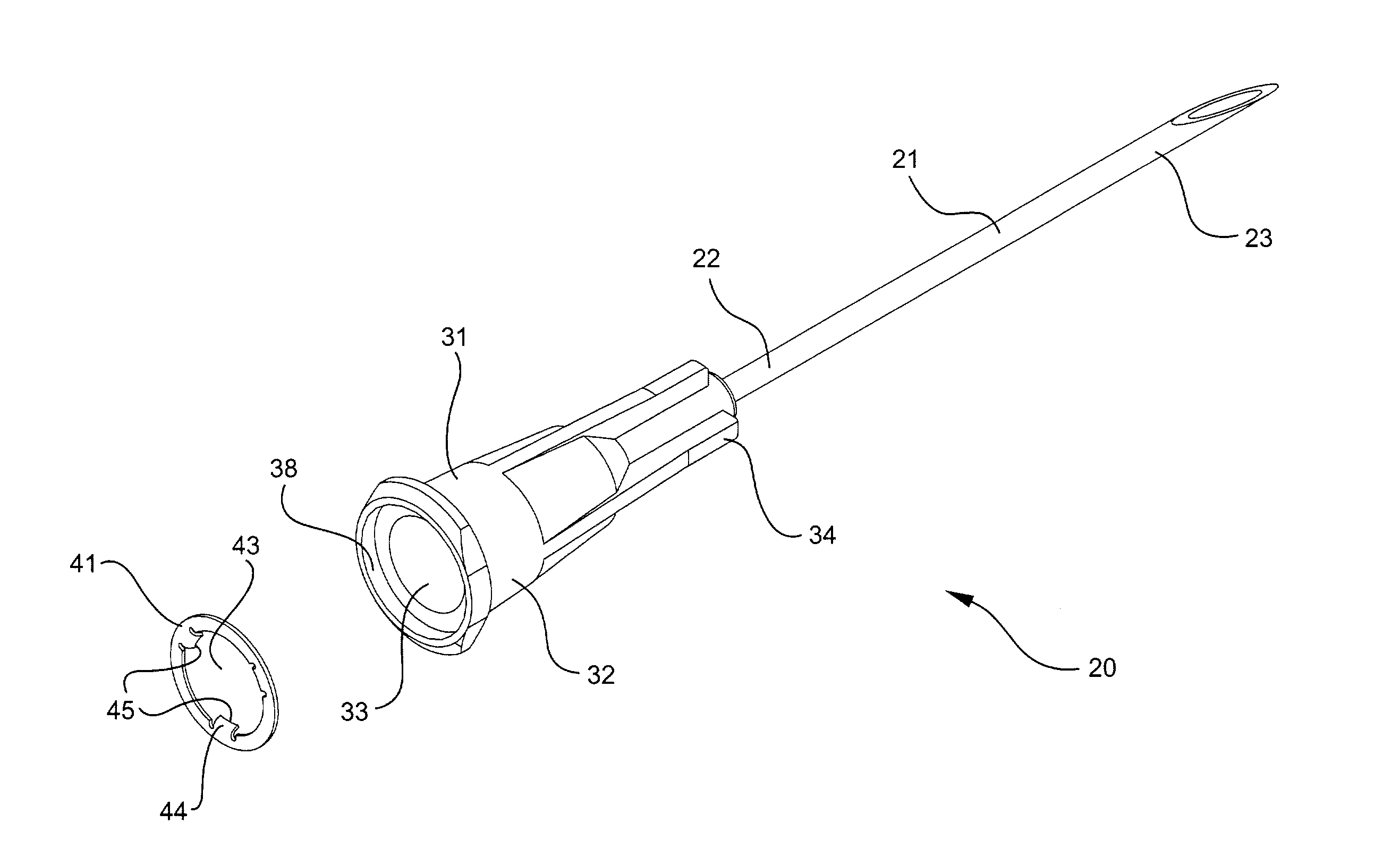
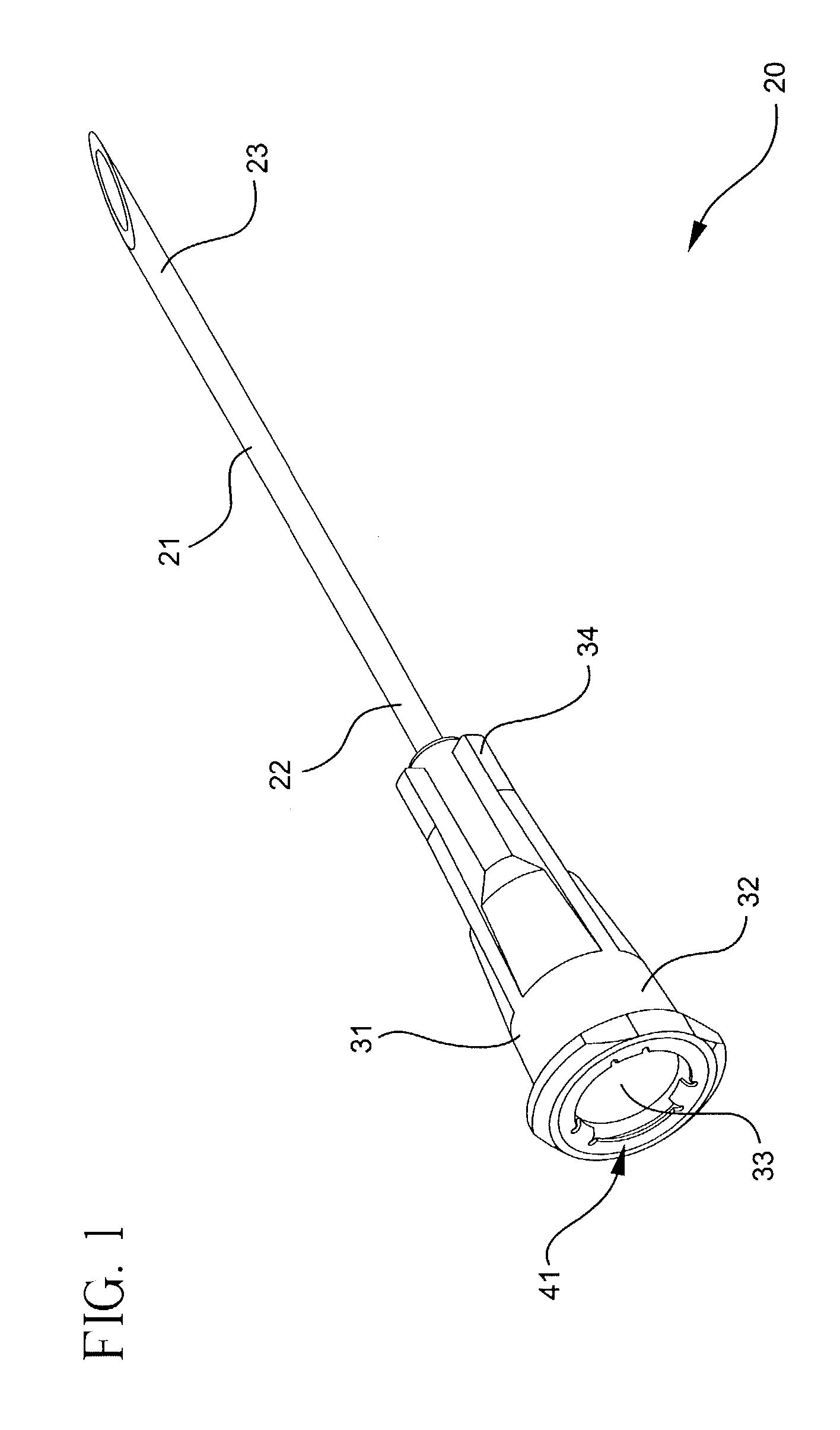
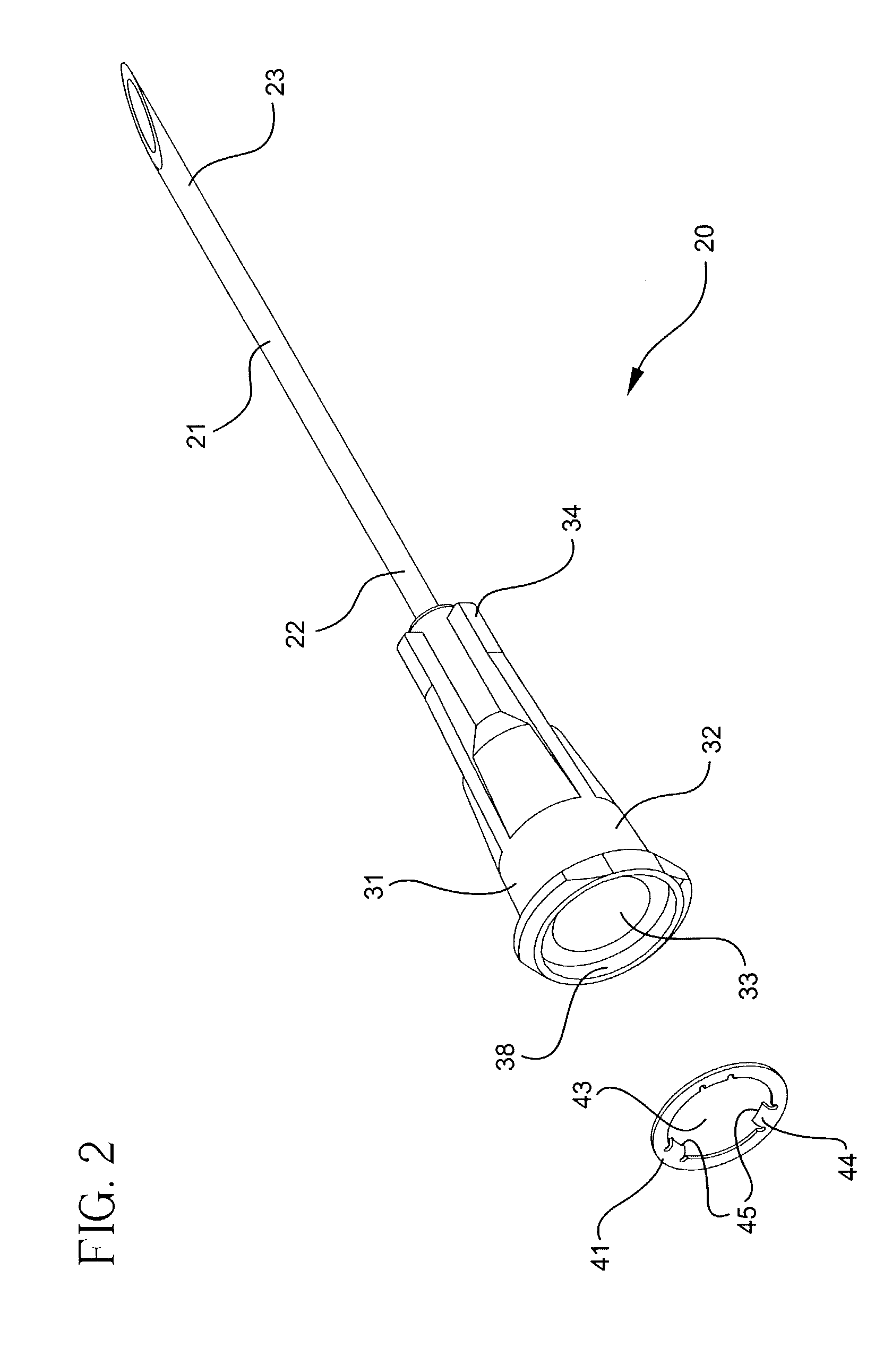
[0030]Referring to FIGS. 1–8, a medical device such as needle assembly 20 includes a needle cannula 21 having a proximal end 22, a distal end 23 and a lumen 24 therethrough defining a longitudinal axis 25. A hub 31 includes an open proximal end 32 with a cavity 33 therein, a distal end 34 and a passageway 35 therethrough. The cavity is part of the passageway. The proximal end of the needle cannula is joined to the distal end of the hub so that the lumen of the needle cannula is in fluid communication with the passageway of ...


PUM


Abstract

A medical device having a releasable retaining includes needle cannula connected to a hub having an open proximal end with a frusto-conically shaped cavity therein. The cavity is part of a passageway through the hub which is in fluid communication with the lumen of the needle cannula. A retaining element is releasably connected to the hub. The hub includes an aperture and at least one protuberance projecting into the aperture for engaging the frusto-conically shaped tip of a fluid delivery device. The protuberance is shaped to offer less resistance to hub movement in a direction of engagement than in a direction of disengagement with the tip. The retaining element is connected to the hub so that when the hub is engaged to the tip, the force required to disengage the retaining element from the tip is greater than the force required to disengage the retaining element from the hub.

Description

FIELD OF THE INVENTION[0001]The present invention relates to a medical device such as a hypodermic needle assembly which is adapted to releasably engage a fluid transfer device such as a syringe. In particular, the present invention relates to a medical device such as a hypodermic needle assembly having a releasable retaining element for improving the connection between a needle assembly and a syringe.BACKGROUND[0002]A hypodermic syringe consists of a cylindrical barrel, most commonly made of thermoplastic material or glass, with a distal end adapted to be connected to a hypodermic needle and a proximal end adapted to receive a stopper and plunger rod assembly. The stopper provides a relatively air-tight seal between itself and the syringe barrel so that movement of the stopper up and down the barrel will cause liquid, blood or other fluids to be drawn into or forced out of the syringe through the distal end. The stopper is moved along the syringe barrel by applying axial force on a...

Claims


Application Information

Patent Timeline
IPC IPC(8): A61M5/00A61M5/158A61B17/20A61M5/178A61M5/32A61M5/34
CPCA61M5/3216A61M5/346A61B17/205A61M5/3269A61M5/3275A61M5/347Y10S604/905E01D22/00E01D2/02E01D2101/268
Inventor CAIZZA, RICHARD J.
Owner BECTON DICKINSON & CO
Features
  • Generate Ideas
  • Intellectual Property
  • Life Sciences
  • Materials
  • Tech Scout
  • Unparalleled Data Quality
  • Higher Quality Content
  • 60% Fewer Hallucinations
Learn More