Motorized barrier operator system for setting a down force adjustment to a minimum value and method for programming the same

a technology of operator system and down force adjustment, which is applied in the direction of motor/generator/converter stopper, dynamo-electric converter control, instruments, etc., can solve the problems of entrapped objects or doors, affecting the operation of the operator system, and taking some time and effort to adjust the setting properly

Inactive Publication Date: 2006-10-03
WAYNE DALTON CORP
View PDF11 Cites 33 Cited by
  • Summary
  • Abstract
  • Description
  • Claims
  • Application Information

AI Technical Summary

Problems solved by technology

This repeated cycling may take some time and effort to adjust the setting properly for each weight and size door a particular type of operator is associated with.
The setting may also be adjusted by untrained personnel and if no warranty maintenance is ever performed, the setting will likely be left at an exceedingly high and dangerous value.
As a result, when the unnecessarily high force is used, the entrapped object or the door, or both, are damaged.
The automatic internal force adjustment solves these problems, but the units that incorporate this type of technology may not work with all weights and sizes of doors.
But this configuration does not provide any type of user feedback.
As such, the user is never quite sure if just the minimum force required to close the barrier is being used.
The unit monitors the operational characteristics of the operator and determines the proper force adjustment in both the up and down directions compared to predetermine thresholds and will not allow user adjustment.
But, this system is deficient in that it does not provide for any user feedback when setting the down force value used by the controller.
Although effective in its stated purpose, it is believed that an excessive amount of force may still be applied to an obstruction inasmuch as the force applied may still be more than required to actually close the door.
Moreover, no user feedback mechanism is provided such that the user can determine what the minimum force setting is during a programming mode.

Method used


Image

  • Motorized barrier operator system for setting a down force adjustment to a minimum value and method for programming the same
  • Motorized barrier operator system for setting a down force adjustment to a minimum value and method for programming the same
  • Motorized barrier operator system for setting a down force adjustment to a minimum value and method for programming the same

Examples


Embodiment Construction

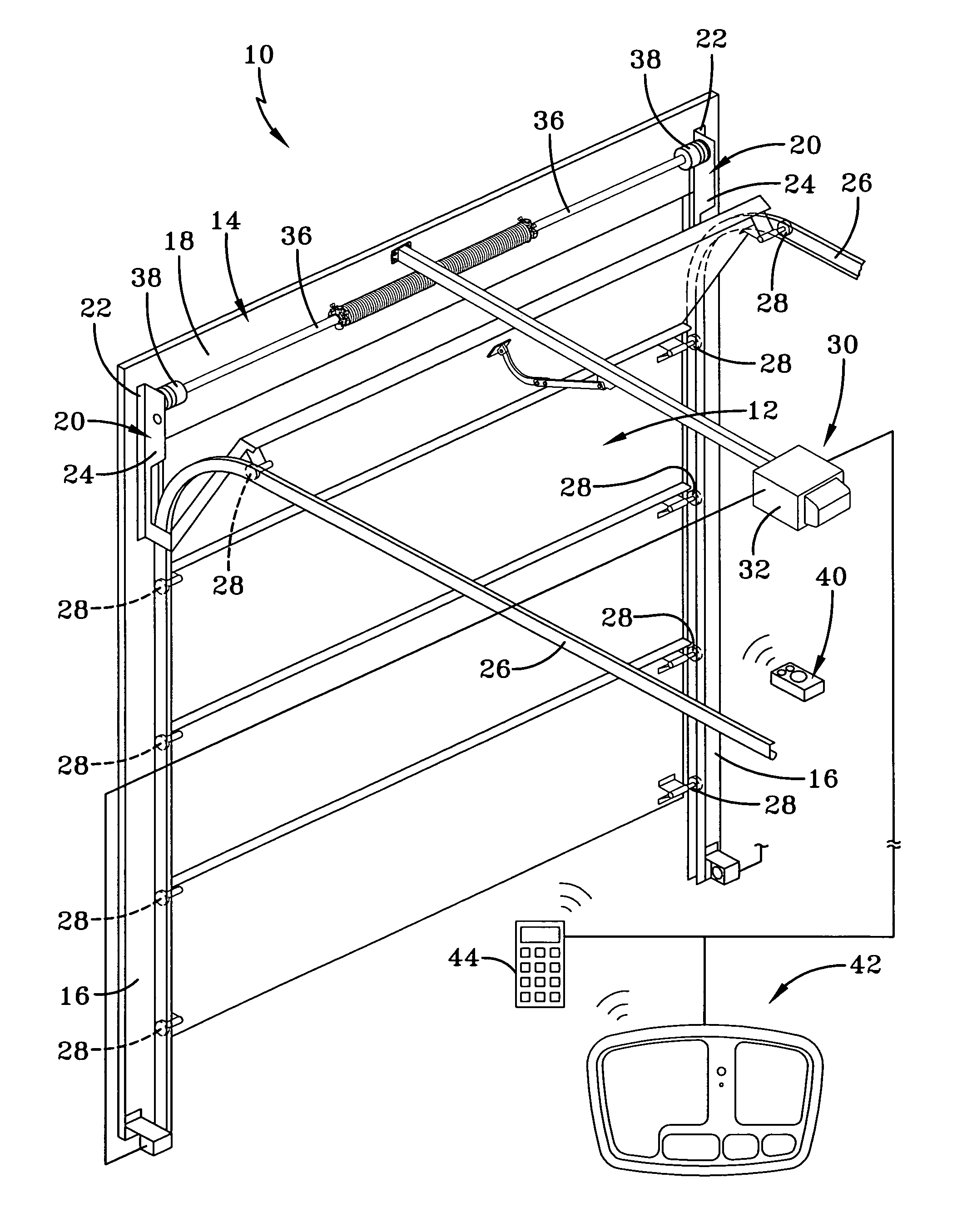
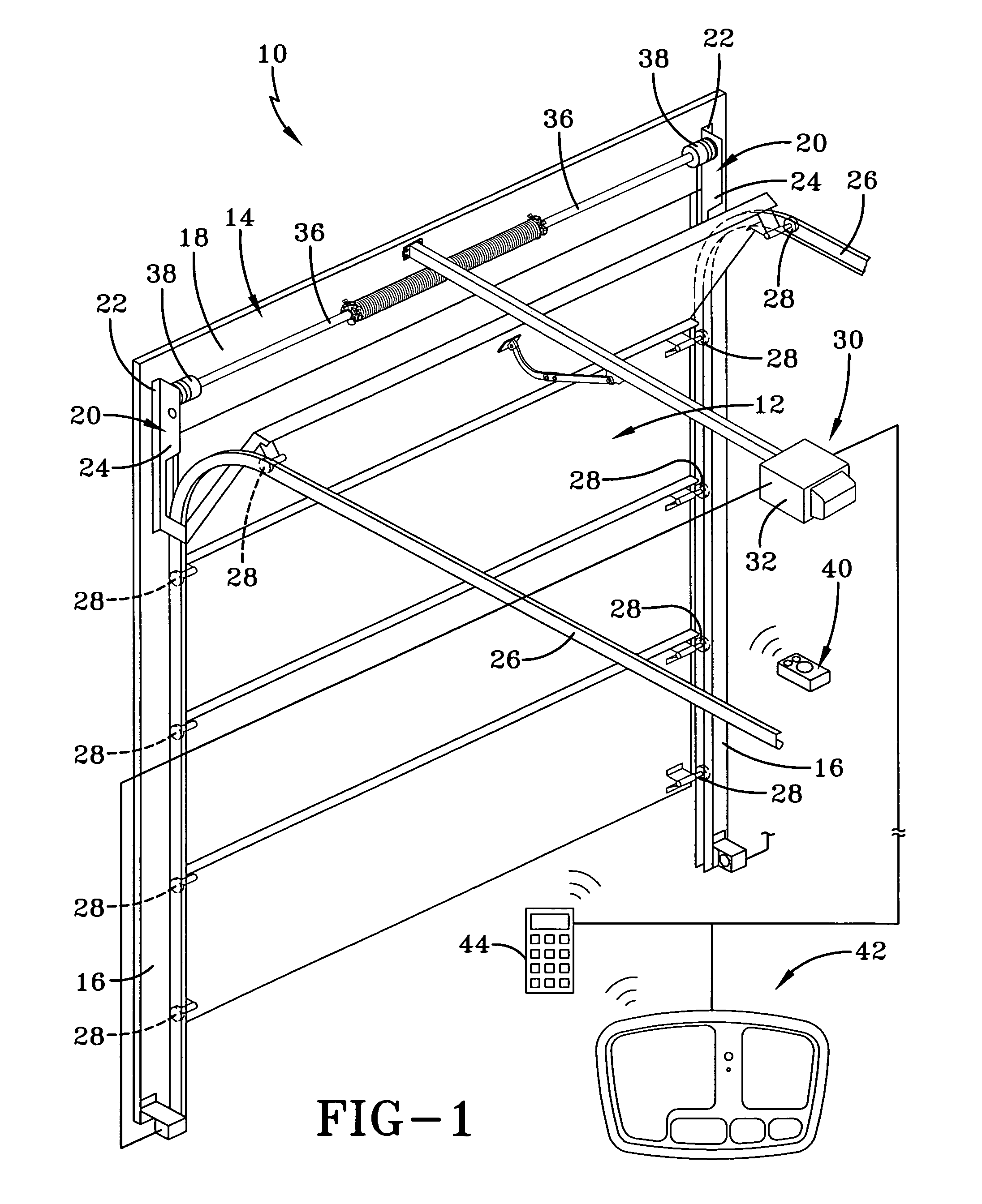
[0017]A motorized barrier operator adaptable to different safety configurations is generally indicated by the numeral 10 in FIG. 1 of the drawings. The system 10 is employed in conjunction with a conventional sectional garage barrier or door generally indicated by the numeral 12. The teachings of the present invention are equally applicable to other types of movable barriers such as single panel doors, gates, windows, retractable overhangs, and any device that at least partially encloses an area. The door 12 is most likely an anti-pinch type door. The opening in which the door is positioned for opening and closing movements relative thereto is surrounded by a frame, generally indicated by the numeral 14, which consists of a pair of a vertically spaced jamb members 16 that, as seen in FIG. 1, are generally parallel and extend vertically upwardly from the ground (not shown). The jambs 16 are spaced and joined at their vertically upper extremity by a header 18 to thereby form a general...


PUM


Abstract

A method and system for setting a downward force adjustment exerted by a barrier is disclosed. As is known, the barrier operator initiates corrective action if a detected obstruction force is deemed excessive. The inventive method and system comprises pre-setting a force threshold value used by the barrier operator. While in a programming mode, the barrier is moved from one limit position to another limit position. A recorded value is determined during the moving of the barrier and the threshold value is adjusted until equal the recorded value. A feedback device such as a light or a speaker is used to indicate when the threshold value is at least equal the recorded value.

Description

TECHNICAL FIELD[0001]Generally, the present invention relates to a movable barrier operator system for use on a closure member moveable relative to a fixed member. More specifically, the present invention relates to a barrier operator, wherein the operator allows for manual setting of a down force adjustment to determine the minimum force needed to move the barrier.BACKGROUND ART[0002]For convenience purposes, it is well known to provide garage doors which utilize a motor to provide opening and closing movements of the door. Motors may also be coupled with other types of movable barriers such as gates, windows, retractable overhangs and the like. An operator is employed to control the motor and related functions with respect to the door. The operator receives command signals for the purpose of opening and closing the door from a wireless remote, from a wired or wireless wall station or other similar device. It is also known to provide safety devices that are connected to the operato...

Claims


Application Information

Patent Timeline
Patent Type & Authority Patents(United States)
IPC IPC(8): G05B5/00G05D3/00H02H7/08H02P1/04H02P3/00
CPCG05B19/4061H02H7/0851H02P1/04E05Y2400/58E05Y2900/106G05B2219/34464G05B2219/45242E05F15/668E05Y2800/00E05F15/41H02H3/006
Inventor MURRAY, JAMES SGAGNON, RICHARD E
Owner WAYNE DALTON CORP
Why Eureka
Try Eureka