Leakage transformer

a leakage transformer and transformer technology, applied in the direction of transformer/inductance details, coils, inductances, etc., can solve the problems of large leakage transformers, leakage transformers may be damaged, and the risk of short-circuit occurring between one end and the other end, so as to reduce the height of leakage transformers and reduce the manufacturing cost of leakage transformers

Inactive Publication Date: 2006-10-03
SUMIDA CORP
View PDF11 Cites 12 Cited by
  • Summary
  • Abstract
  • Description
  • Claims
  • Application Information

AI Technical Summary

Benefits of technology

[0008]The present invention is made in view of the above-described situation, and an object thereof is to provide a leakage transformer that is capable of preventing occurrence of a short-circuit of a secondary winding and is also capable of restraining a distance between terminals from becoming wide.
[0029]According to the present invention, lowering of a height of a leakage transformer can be realized. Further, a manufacturing cost of the leakage transformer can be reduced.

Problems solved by technology

Accordingly, when dust or the like adheres to the two terminals to which are connected the one end and the other end of the secondary winding to bridge them, there is a risk of short-circuit occurring between the one end and the other end, which are the high voltage side and the low voltage side of the secondary winding.
When such a short-circuit occurs, the leakage transformer may be damaged since the potential difference between the one end and the other end of the secondary winding is high.
However, when such a structure with a widened distance is adopted, the leakage transformer becomes wide, so that the leakage transformer itself becomes large.
As a result, such a case goes against a request of making the leakage transformer smaller.

Method used


Image

  • Leakage transformer
  • Leakage transformer
  • Leakage transformer

Examples


Embodiment Construction

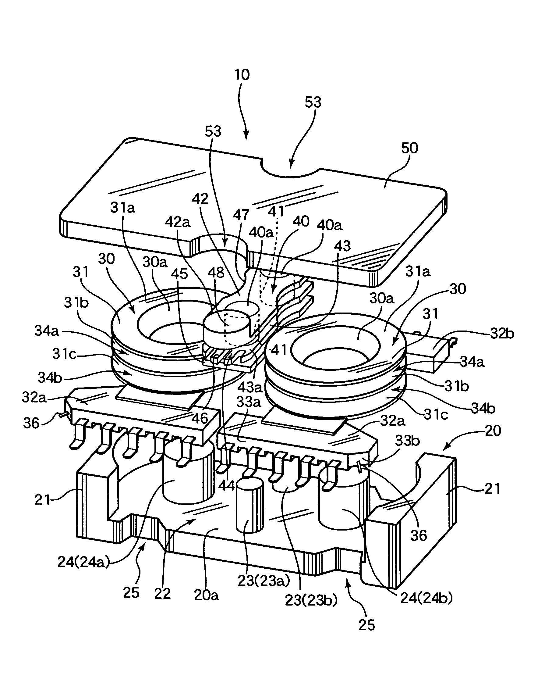
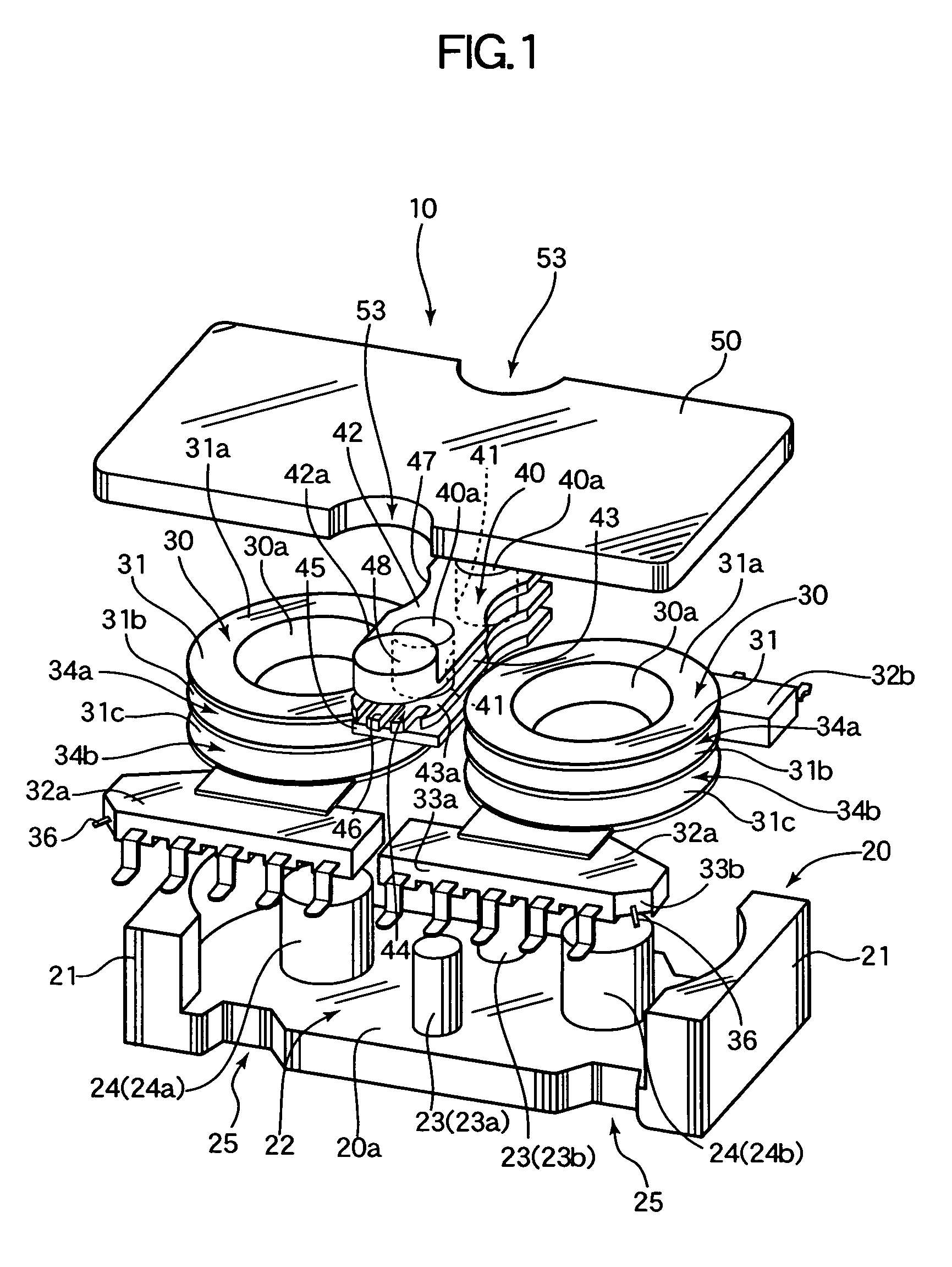
[0042]Hereinafter, a leakage transformer according to one embodiment of the present invention will be described based on FIG. 1 to FIG. 12. FIG. 1 is an exploded perspective view showing the structure of a leakage transformer 10, and FIG. 2 is a perspective view showing the entire leakage transformer 10. Further, FIG. 3 shows a plan view, FIG. 4 shows a front view, FIG. 5 shows a side view, and FIG. 6 shows a rear view of the leakage transformer 10.

[0043]The leakage transformer 10 has, as shown in FIG. 1, a case core 20, two-step coil bobbins 30, an adjustment coil bobbin 40, and a cover core 50 as major components. The case core 20 and the cover core 50 are constituted of a magnetic material having an insulation characteristic. An example of the magnetic material is a nickel-based ferrite core. However, the material of the case core 20 and the cover core 50 is not limited thereto, which maybe other magnetic material such as a permalloy. Further, the two-step coil bobbins 30 and the...


PUM

PropertyMeasurementUnit
angleaaaaaaaaaa
slant angleaaaaaaaaaa
angleaaaaaaaaaa

Abstract

A leakage transformer capable of preventing occurrence of a short-circuit of a secondary winding and is also capable of restraining a distance between terminals from becoming wide is provided. A leakage transformer (10) has a structure such that a secondary winding (71) is stacked and arranged in a height direction with respect to a primary winding (70), and comprises a plurality of primary side terminals (35b to 35e) to which one end and the other end of the primary winding (70) are respectively bound. Further, the leakage transformer (10) comprises a first terminal block (32a) comprising a first wrapping terminal (36) to which one end of the secondary winding (71) is bound and a second terminal block (32b) comprising second wrapping terminals (38b, 38c) to which the other end of the secondary winding (71) is bound.

Description

BACKGROUND OF THE INVENTION[0001]1. Field of the Invention[0002]The present invention relates to a leakage transformer used in a DC / AC inverter circuit or the like, which is used in a lighting circuit or the like of a cold cathode fluorescent lamp (CCFL) in a display device of a television monitor or a personal computer for example.[0003]2. Description of the Related Art[0004]A display device of a personal computer or the like has a lighting circuit of a cold cathode fluorescent lamp. In this lighting circuit, a leakage transformer for driving the display device by applying a high voltage is generally used.[0005]For a leakage transformer of this kind, there exists a structure disclosed in Patent Publication No. 2628524 (refer to Claim 1, paragraphs No. 0010 and 0011, and FIG. 1 and FIG. 5) and in Japanese Patent Application Laid-open No. 2002-299134 (refer to paragraphs No. 0016 and 001, and FIG. 5). In the structure disclosed in these patent documents, one end and the other end of ...

Claims


Application Information

Patent Timeline
Patent Type & Authority Patents(United States)
IPC IPC(8): H01F27/30H01F5/04H01F27/29H01F38/08
CPCH01F27/306H01F38/08H01F5/04H01F27/292
Inventor FUSHIMI, TADAYUKI
Owner SUMIDA CORP
Why Eureka
Try Eureka