
Transmitter circuit and method for modulation distortion compensation

a transmitter circuit and modulation distortion technology, applied in the field of transmitter circuits, can solve the problems of high-linear amplifiers 124/b>, inefficient and power-consuming amplifiers, and inapplicability to portable wireless devices,

Active Publication Date: 2006-10-03
GOOGLE TECHNOLOGY HOLDINGS LLC
View PDF8 Cites 9 Cited by
  • Summary
  • Abstract
  • Description
  • Claims
  • Application Information

AI Technical Summary

Problems solved by technology

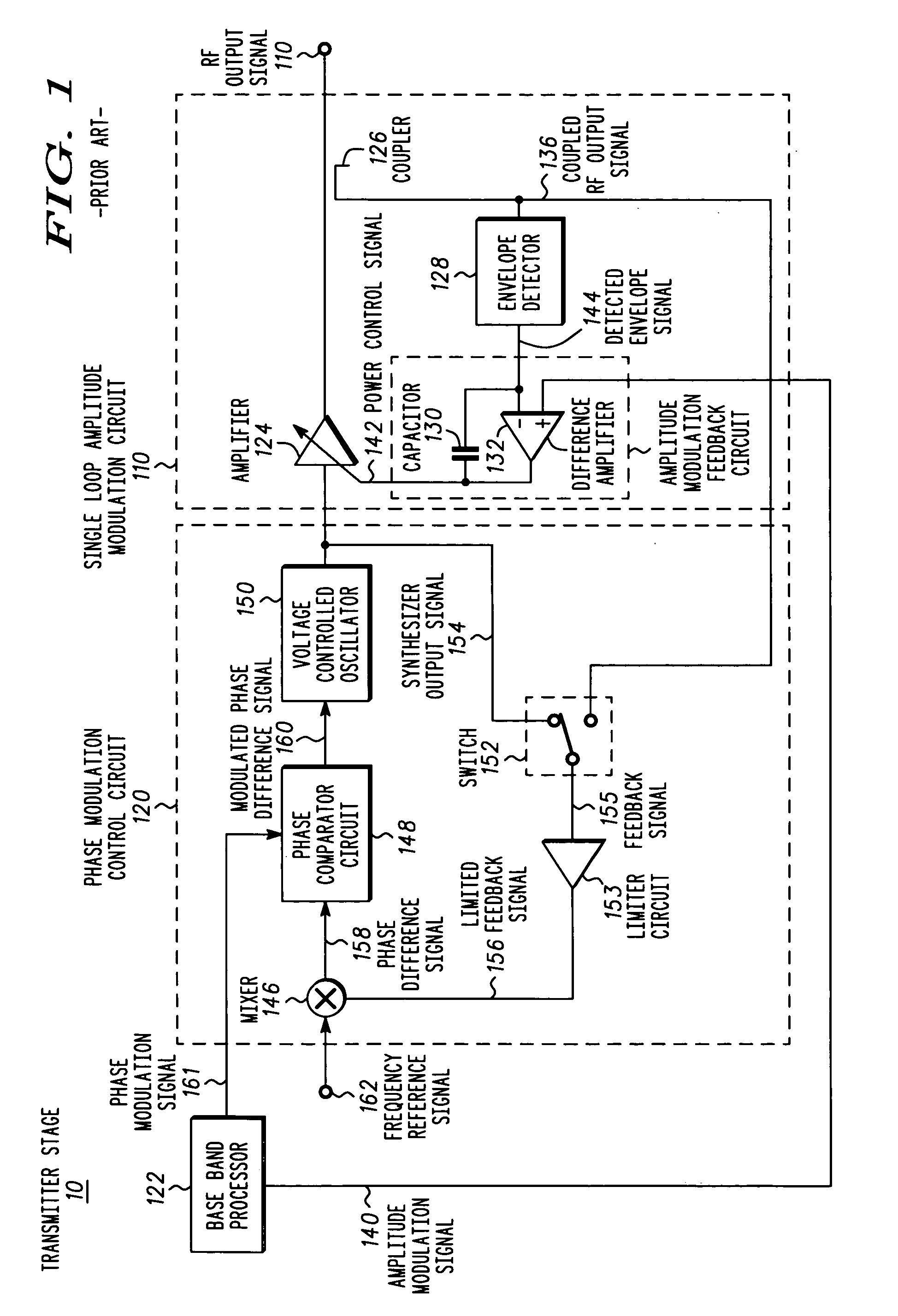
However, such techniques to enhance operating efficiencies may cause phase distortion in the RF output signal 134, resulting in significant errors in a receiver when attempting to receive the phase distorted RF output signal 134.
However, a highly linear amplifier 124 is inefficient and power-consuming and is not desirable for applications such as portable wireless devices.
However, the required degree of phase predistortion is dependent on the RF output signal 134 level, a supply voltage to the amplifier 124, and an operating temperature resulting in a very complex open loop control scheme.
Additionally, the phase predistortion is further complicated when amplitude modulation is employed.
As a result, the single loop amplitude modulation circuit 110 may not sufficiently compensate for the amplitude modulation distortion within amplifier 124 resulting in an RF output signal 134 having excessive amplitude modulation distortion especially at high data rates.

Method used


Image

  • Transmitter circuit and method for modulation distortion compensation
  • Transmitter circuit and method for modulation distortion compensation
  • Transmitter circuit and method for modulation distortion compensation

Examples


Embodiment Construction

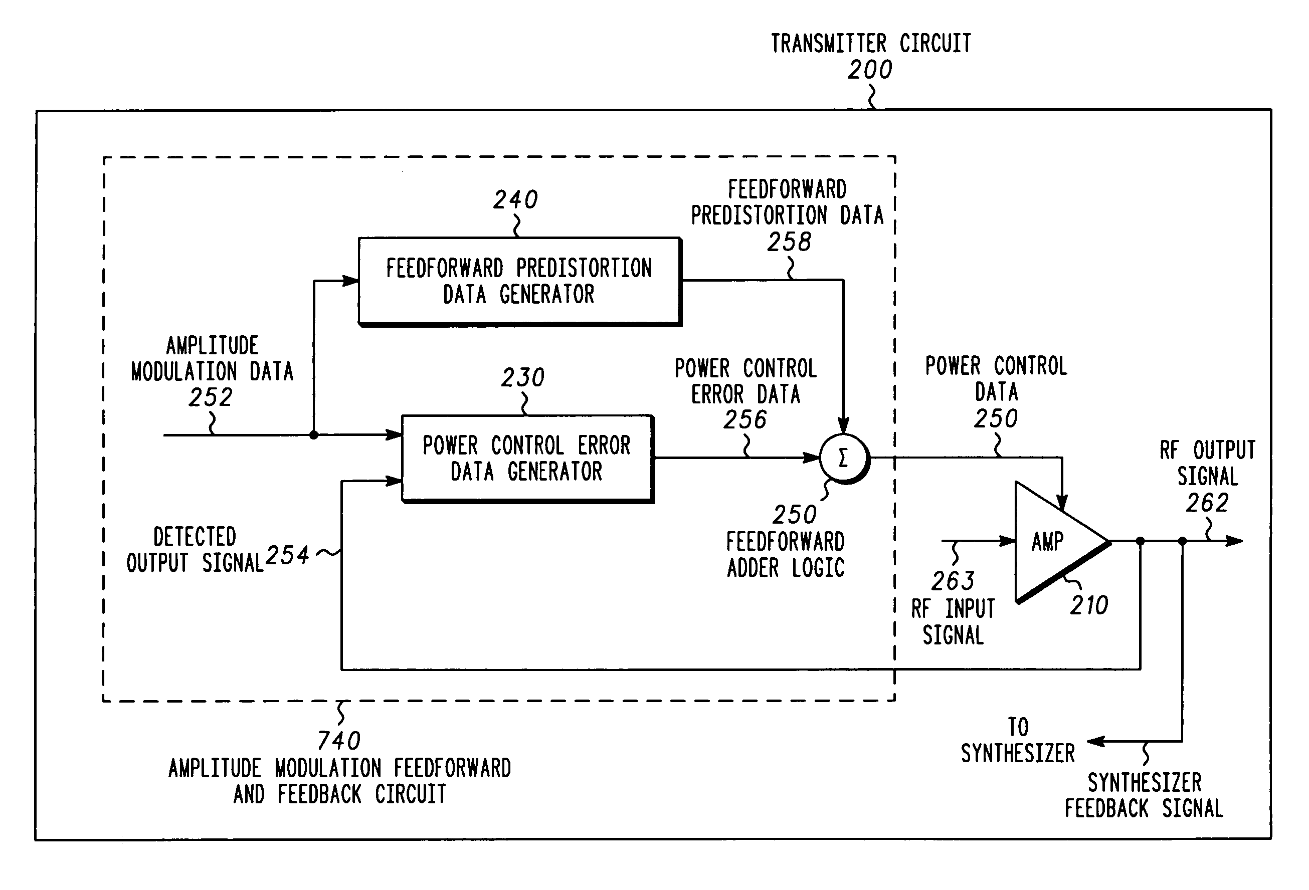
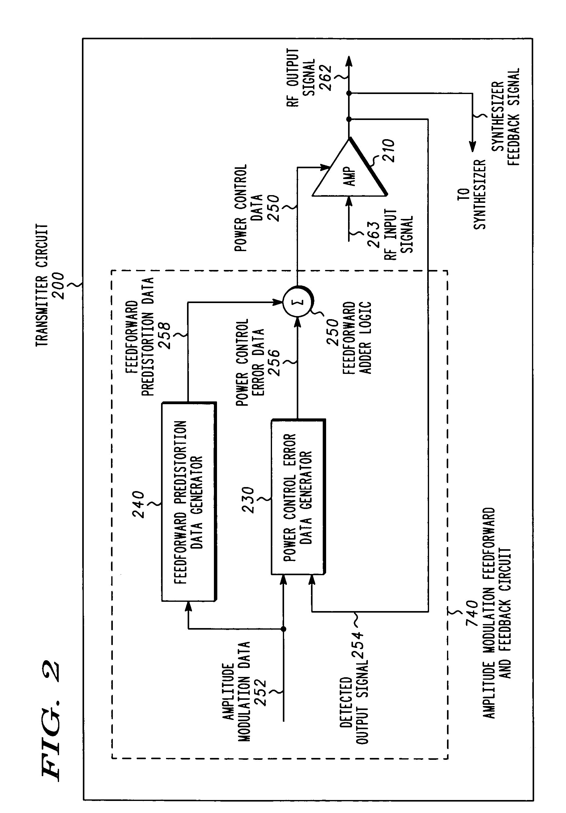
[0018]A transmitter circuit and method reduces amplitude modulation distortion in an amplifier. The transmitter circuit includes a power control error data generator, a feedforward predistortion data generator, feedforward adder logic and an amplifier. The power control error data generator receives amplitude modulation data and an RF coupled output signal and in response produces power control error data. The feedforward predistortion data generator receives the amplitude modulation data and in response produces feedforward predistortion data. The feedforward adder logic receives the power control error data and the feedforward predistortion data and in response produces the power control data. The amplifier receives the power control data and an RF input signal and in response produces an RF output signal. The power control error data generator receives the RF coupled output signal such that the power control data reduces amplitude modulation distortion in the RF output signal.

[00...


PUM


Abstract

A transmitter circuit (200, 400, 510) and method reduces amplitude modulation distortion in an amplifier (210). The transmitter circuit (200, 400, 510) includes a power control error data generator (230), a feedforward predistortion data generator (240), feedforward adder logic (250) and the amplifier (210). The power control error data generator (230) receives amplitude modulation data (252) and an RF coupled output signal (254) and, in response, produces power control error data (256). The feedforward predistortion data generator (240) receives the amplitude modulation data (252) and, in response, produces feedforward predistortion data (258). The feedforward adder logic (250) receives the power control error data (256) and the feedforward predistortion data (258) and, in response, produces power control data (260). The amplifier (210) receives the power control data (260) and an RF input signal (261) and, in response, produces an RF output signal (262), such that the power control data (260) reduces amplitude modulation distortion in the RF output signal (262).

Description

FIELD OF THE INVENTION[0001]The present invention relates generally to a transmitter circuit and, more particularly, to a transmitter circuit to compensate for modulation distortion.BACKGROUND OF THE INVENTION[0002]Many wireless communication protocols provide for transmitters, operating within a communication network, which are capable of employing phase modulation (PM) techniques and (AM) amplitude modulation techniques. Examples of such wireless communication protocols include Enhanced Data Rates for Global Systems for Mobile Communications Evolution (EDGE), Global System for Mobile Communications (GSM), Code Division Multiple Access (CDMA) and Wideband Code Division Multiple Access (WCDMA). To accommodate the modulation requirement for each particular communication protocol, wireless devices such as wireless telephones, wireless personal data assistants (PDAs), pagers, two-way radios and other types of wireless devices employ a transmitter and modulation circuitry for providing ...

Claims


Application Information

Patent Timeline
Patent Type & Authority Patents(United States)
IPC IPC(8): H04B1/04H03C1/06H03C3/09H03F1/32
CPCH03C1/06H03C3/0975H03F1/3241H04B1/04H03F2200/102H03F2200/105H04B2001/0441H03F2201/3227H04B2001/0416H04B2001/0433H03F2201/3221H03F1/34H03F1/3223H03F3/24
Inventor NAGODE, THOMAS D.NANNI, PETERNIGRA, LOUIS M.BLACK, GREG R.TILLEY, KEITH ANDREW
Owner GOOGLE TECHNOLOGY HOLDINGS LLC
Learn More