Method for establishing a three-dimensional representation of a bone from image data

Inactive Publication Date: 2006-10-03
AO TECH AG
View PDF11 Cites 172 Cited by
  • Summary
  • Abstract
  • Description
  • Claims
  • Application Information

AI Technical Summary

Benefits of technology

[0015]The method may comprise step of loading a set of image data of a surgical tool. The image data may be loaded into a processor of the computer. The surgical tool may be represented at the display means preferably together with the virtual representation of a respective bone or bone fragment. The virtual representation and / or the representation of the surgical tool may be displaced on the display means by using a control means connected to the computer.
[0016]The method may comprise loading a set of image data of a surgical implant into the processor of the computer. The surgical implant may be represented at the display means preferably together with the virtual representation of a respective bone or bone fragments. The virtual representation and the representation of the surgical implant may be displaced on the display means by using a control means.
[0017]The method may comprise rotating the virtual representation on the display means, such as by using a control means in order to receive a perspective view of the region of interest of a bone or bone fragments. A surgical action may be simulated at the display means such as by means of adjusting the virtual representation and arranging the surgical implant at its desired position.

Problems solved by technology

Known methods have the disadvantage that CT-scanning delivers cross-sectional images of the patient body whereas fluoroscopic X-ray images deliver two-dimensional images and, therefore, many X-ray images are required in several parallel planes and under several different angles of the radiation source to obtain a three-dimensional model.

Method used


Image

  • Method for establishing a three-dimensional representation of a bone from image data
  • Method for establishing a three-dimensional representation of a bone from image data
  • Method for establishing a three-dimensional representation of a bone from image data

Examples


Embodiment Construction

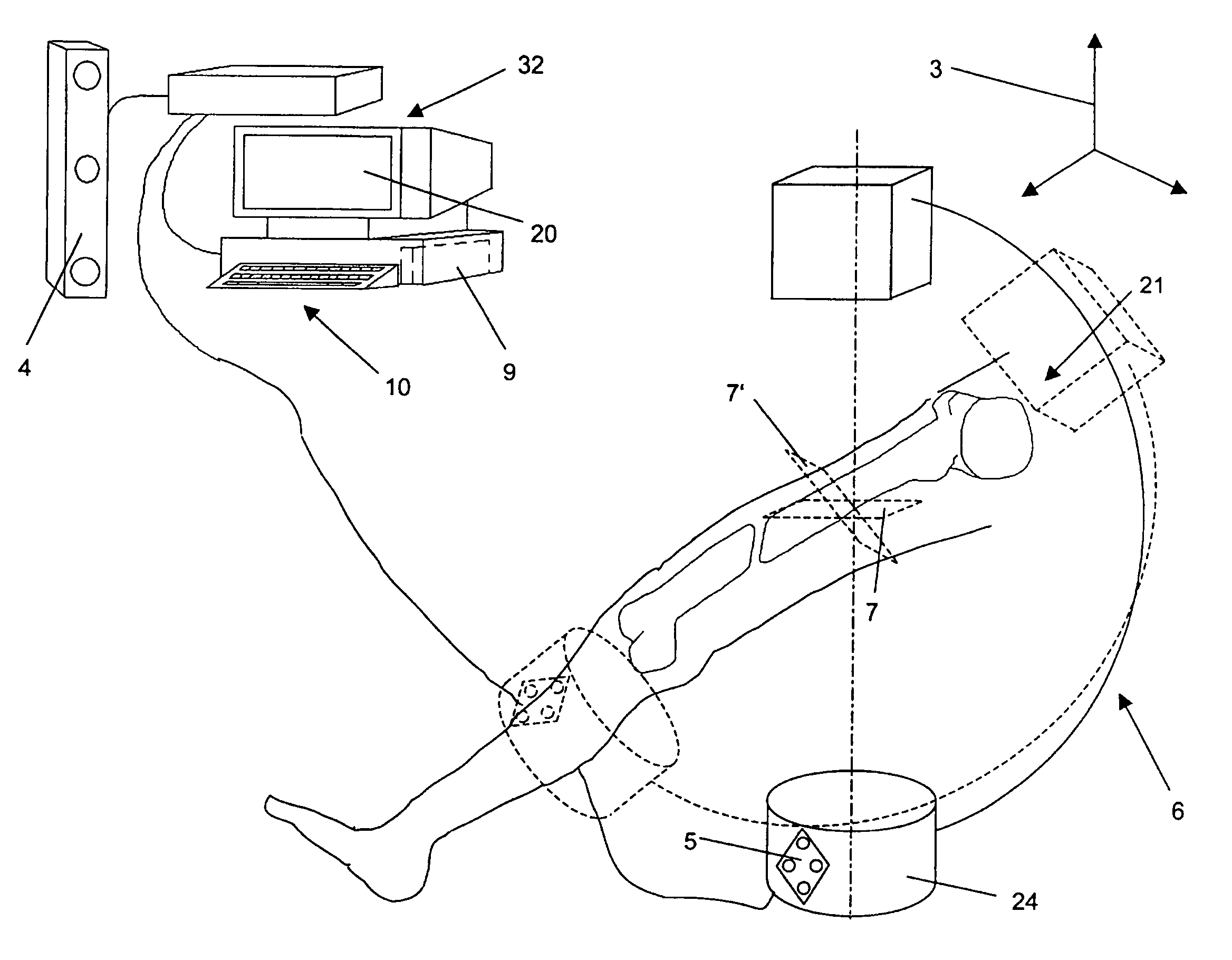
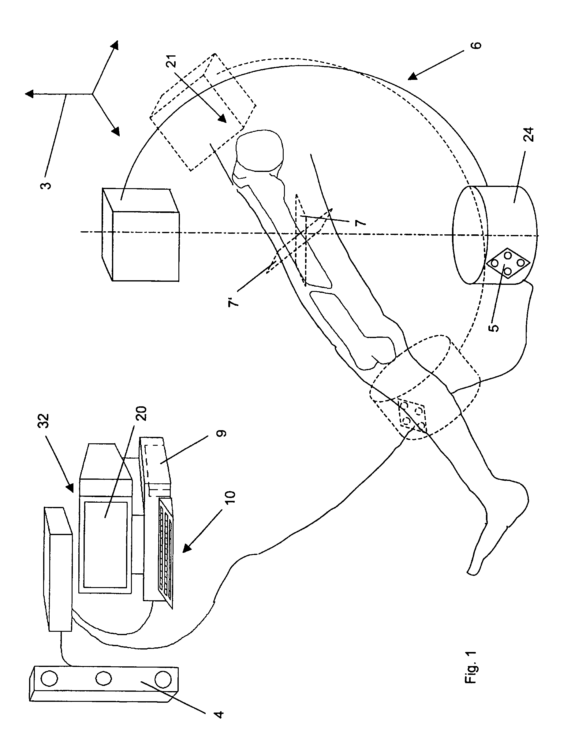
[0029]One aspect of the present invention relates to a method for establishing a virtual three-dimensional representation (3D model) from imaging data, such as X-ray images. At least some or all of the imaging data may be two-dimensional. In one embodiment, the method comprises positioning an imaging device, such as an X-ray device such that the region of interest at the patient's body may be mapped onto a plane of projection of the imaging device. The region of interest may be a portion of a patient's bone. At least one first medical image of the region of interest is mapped onto the plane of projection. The at least one first medical image may be stored as a set of image data in a data storage means of a computer. The image may comprise pixels, for example, a matrix of 1282 to 10242 pixels.

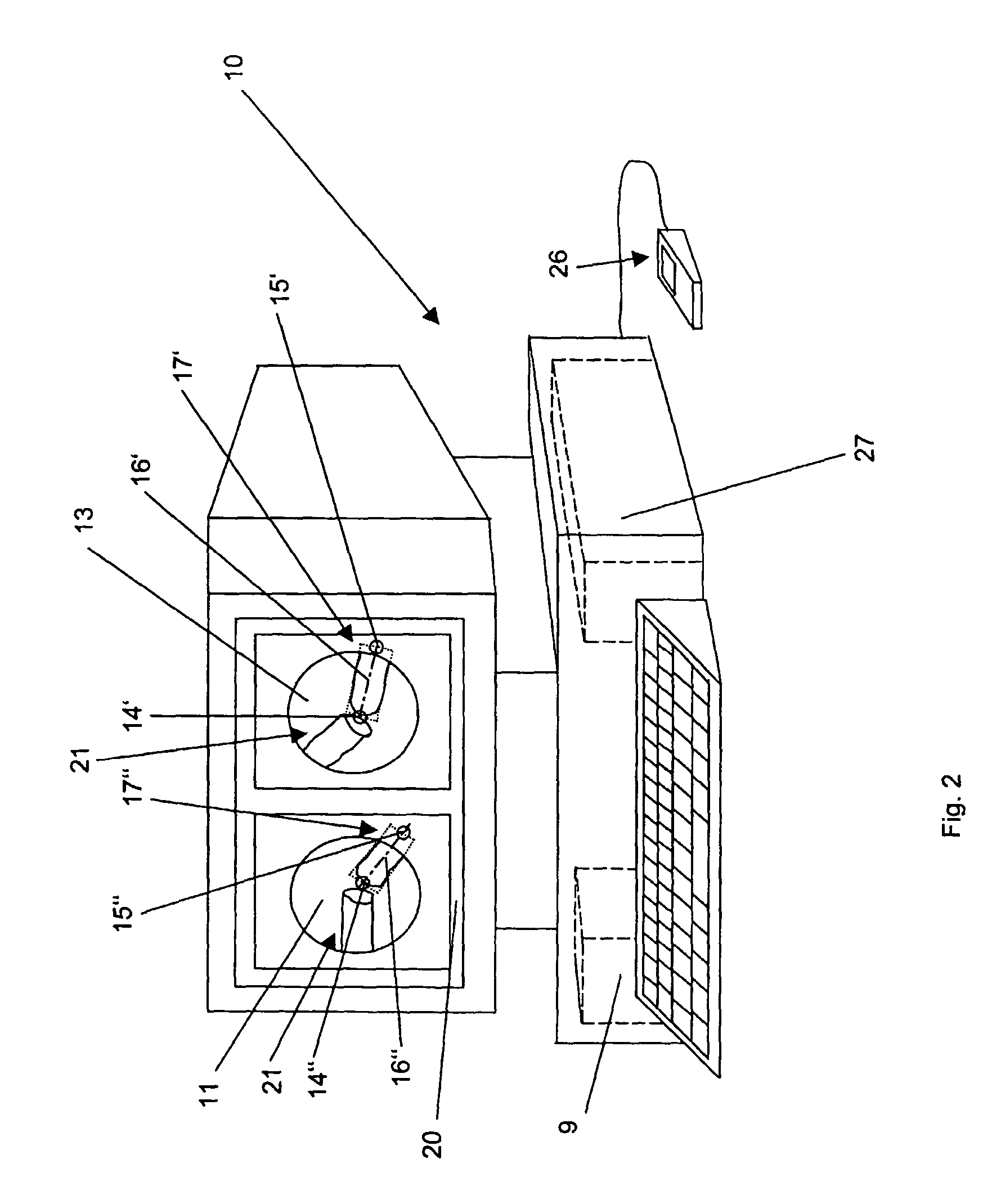
[0030]The at least one first medical image may be displayed to a display means in communication with the computer. The display means may be a head mounted display. A three-dimensional virtual re...


PUM


Abstract

A system and method for preparing a virtual three-dimensional representation of a first portion of a bone. The method may comprise obtaining, from a first orientation with respect to the first portion of the bone, first image data of the first portion of the bone and obtaining, from a second, different orientation with respect to the first portion of the bone, second image data of the first portion of the bone. A three-dimensional (3D) virtual representation of the first portion of the bone may be generated. The 3D virtual representation of the first portion of the bone may be displayed. The displayed 3D virtual representation may have an orientation, determined using at least the difference between the first and second orientations from which the first and second image data were obtained.

Description

RELATED APPLICATIONS[0001]The present application is a continuation of international application no. PCT / CH01 / 00086, filed 7 Feb. 2001, which application is incorporated herein by reference.FIELD OF THE INVENTION[0002]The present invention relates to a method for preparing a three-dimensional representation of a bone or portion thereof from imaging data.BACKGROUND OF THE INVENTION[0003]Computer assisted surgery systems (CAS systems) or image guided surgery systems that are provided with a computer and a position measurement device in order to measure the position of surgical instruments, devices and a body portion of the patient are often used to perform minimally invasive surgery. Computer assisted surgery systems (CAS-systems) are disclosed e.g. in EP 0 359 773 to Schlöndorff, U.S. Pat. No. 5,383,454 to Buchholz and in U.S. Pat. No. 5,682,886 Delp. CAS systems may comprise a memory means to store medical images such as e.g. X-rays, computertomographs or MR images (magnetic resonan...

Claims


Application Information

Patent Timeline
Patent Type & Authority Patents(United States)
IPC IPC(8): A61B5/05A61B6/00A61B6/02A61B34/10A61B34/20A61B90/00
CPCA61B6/4441A61B6/463A61B6/466A61B6/505A61B6/547A61B19/52A61B19/5244A61B5/1114A61B19/56A61B2019/502A61B2019/505A61B2019/5255A61B2019/5272A61B2019/5291A61B2034/102A61B90/36A61B2034/2055A61B2034/2072A61B34/20A61B34/25A61B2034/105A61B2090/365A61B6/03
Inventor ZHENG, GUOYANNOLTE, LUTZ-PETER
Owner AO TECH AG
Why Eureka
Try Eureka