Bottom fish rig

Active Publication Date: 2006-10-10
BRZOZOWSKI FR T
View PDF19 Cites 20 Cited by
  • Summary
  • Abstract
  • Description
  • Claims
  • Application Information

AI Technical Summary

Benefits of technology

[0024]It is therefore an object of the present embodiment of the invention to provide a new and improved bottom fish rig that has all of the advantages of the prior art fishing tackle and none of the disadvantages.
[0025]It is another object of the present embodiment of the invention to provide a new and improved bottom fish rig that may be easily and efficiently manufactured and marketed.
[0026]An even further object of the present embodiment of the invention is to provide a new and improved bottom fish rig that has a low cost of manufacture with regard to both materials and labor, and which accordingly is then susceptible of low prices of sale to the consuming public, thereby making such bottom fish rig economically available to the buying public.
[0027]Still another object of the present embodiment of

Problems solved by technology

However, the Hnizdor '852 patent does not have a removable sliding weight with movement stops and a horizontal unilateral 3-prong hook that resists snagging.
However, the Petrasek '947 patent does not have a removable sliding weight with movement stops and a horizontal unilateral 3-prong hook that resists snagging.
However, the Carlson '178 patent does not have a removable sliding weight with movement stops and a horizontal unilateral 3-prong hook that resists snagging.
However, the Lewis '910 patent does not have a removable sliding weight with movement stops and a horizontal unilateral 3-prong hook that resists snagging.
However, the Snyder '508 patent does not have a removable

Method used


Image

  • Bottom fish rig
  • Bottom fish rig
  • Bottom fish rig

Examples


second embodiment

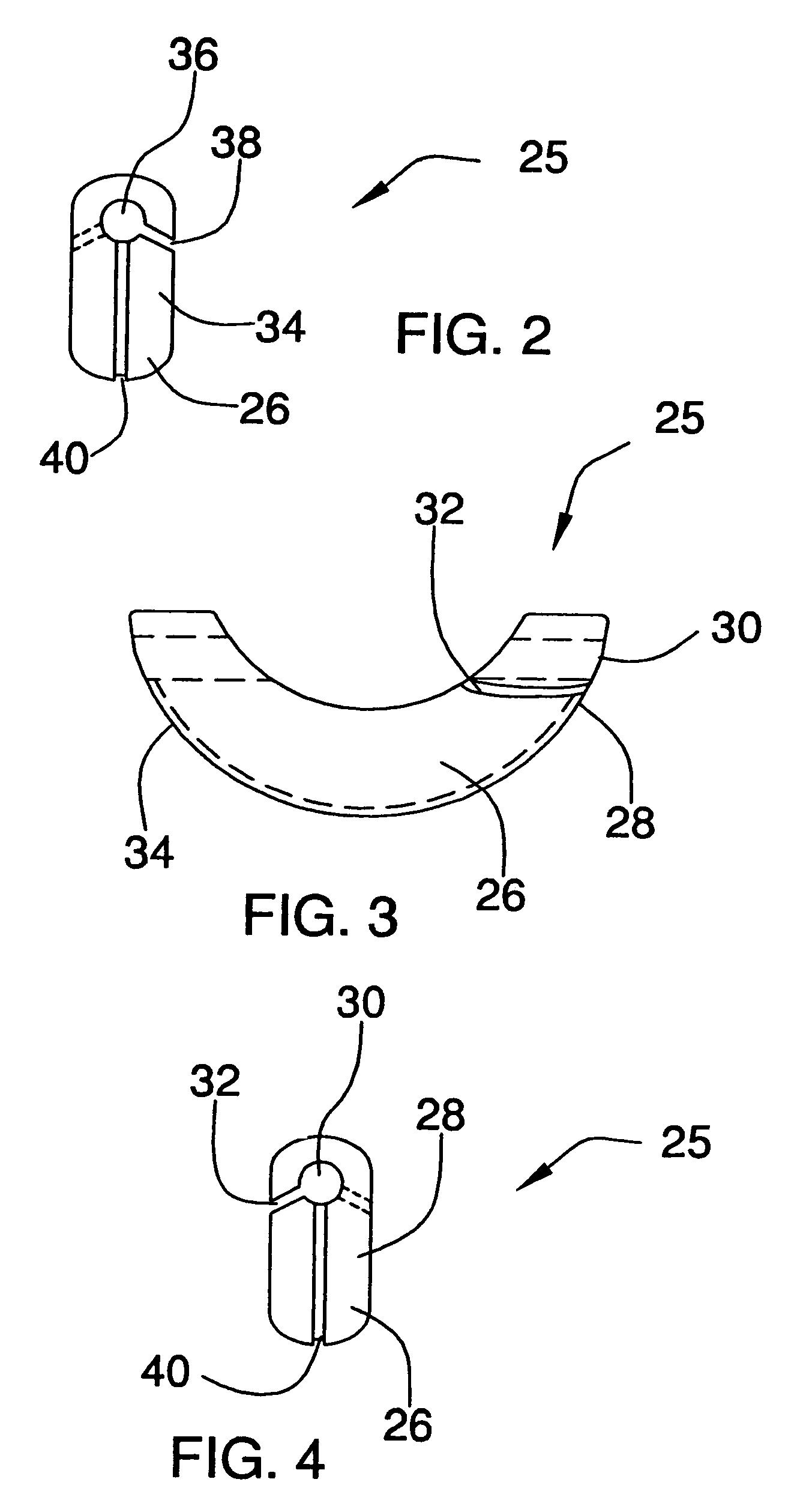
[0059]Another difference in the second embodiment in FIG. 5 through FIG. 8 the c-weight first end 28 has the first slot on the right side; and an a-frame-shaped inclined second slot 38 on the second end on the left side. The shape of a first slot 32 and a second slot 38, with the different inclines hinder the c-weight 12 from working its way off of the leader 13. The slots 32 and 38 could be formed into other geometric shapes to make small obstacles to prevent the leader for accidentally working its way out of the first bore 30 and the second bore 36.

[0060]In FIG. 5 a second embodiment of the removable sliding c-weight of a bottom fish rig is illustrated and will be described from a top left perspective view. The removable sliding c-weight 25 has substantially the c-shape with three main sections, a first end 28, a c-weight hull 26, and a second end 34 with a new feature a c-weight hull hole 27. The c-weight 25 has a first end 28 with a first bore 30 that has a space to the first sl...

fourth embodiment

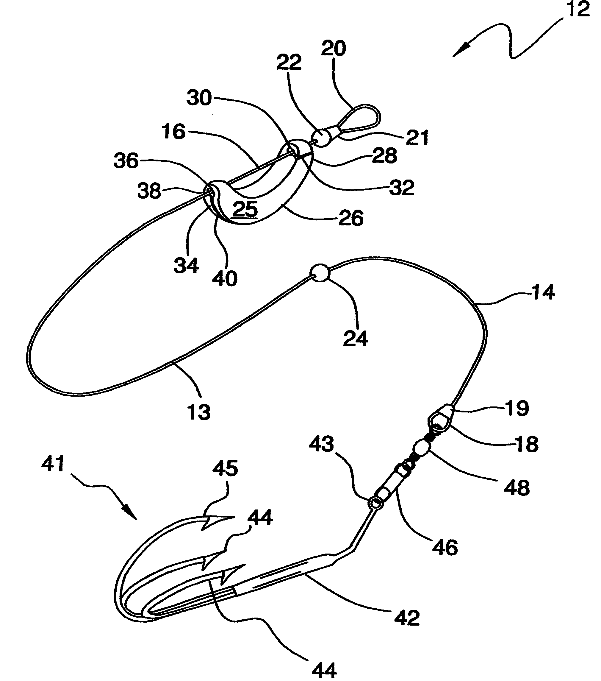
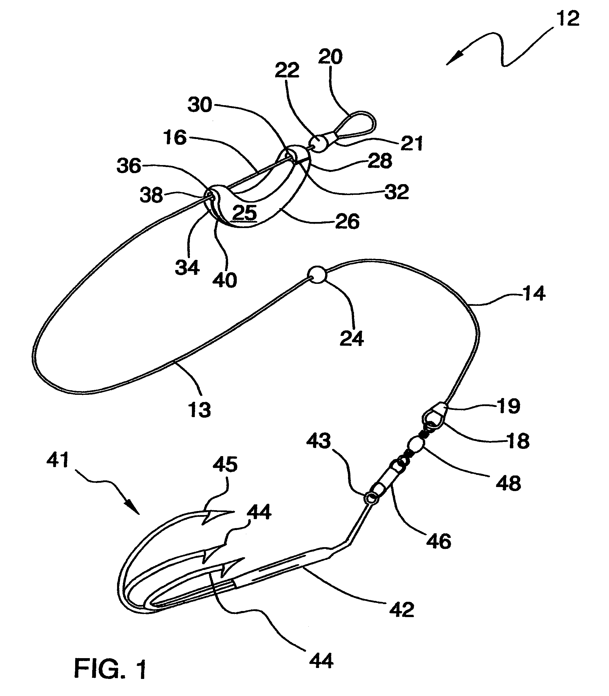
[0066]In FIG. 10, a fourth embodiment, a horizontal unilateral three-pronged hook 41 of the bottom fish rig 12 is illustrated and will be described. A horizontal unilateral three-pronged hook 41 has a shorter vertical center hook barb 45 and a pair of symmetrical outer hook barbs 44 which are disposed within the 180 degree section. This upward and inward placement of the barbs 44 allows the horizontal unilateral three-pronged hook 41 to slide without snagging.

fifth embodiment

[0067]In FIG. 11, a fifth embodiment, a horizontal unilateral three-pronged hook 41 of the bottom fish rig 12 is illustrated and will be described. A horizontal unilateral three-pronged hook 41 has a longer vertical center hook barb 45 and a pair of symmetrical outer hook barbs 44 which are located within the 180 degree section. This upward and inward placement of the barbs 44 allows the horizontal unilateral three-pronged hook 41 to slide without snagging and to flip upright as the leader is being reeled.

[0068]While a preferred embodiment of the bottom fish rig has been described in detail, it should be apparent that modifications and variations thereto are possible, all of which fall within the true spirit and scope of the invention. With respect to the above description then, it is to be realized that the optimum dimensional relationships for the parts of the invention, to include variations in size, materials, shape, form, function and manner of operation, assembly and use, are ...


PUM


Abstract

The bottom fish rig 12 has a strong leader 13 with a removable sliding c-weight 25 and a horizontal unilateral three-pronged hook 41 that resists snagging and reduces possible injuries. A horizontal unilateral three-pronged hook 41 differs from the standard treble hook by having all three barbs oriented upwards in a 180-degree plane and the hook 41 is designed to lie flat on the surface. An elongated leader 13 has a hook end 14 and a line end 16. The hook end 14 has a leader hook loop 18 and the leader line end 16 has a leader line loop 20. A first movement stop 22 is crimped to the leader 13 before the leader line loop 20. A second movement stop 24 is crimped to the leader about two-thirds of the length. A sliding c-weight 25 connects to the leader 13 between movement stops.

Description

[0001]This application claims the benefit of provisional application No. 60 / 430,325, filed Nov. 30, 2002.BACKGROUND OF THE INVENTION[0002]1. Field of the Invention[0003]The present embodiment of the invention relates to a bottom fish rig for use in connection with fishing tackle. The bottom fish rig has particular utility in connection with fishing tackle by having a strong leader with a notable new removable sliding weight and a horizontal unilateral three pronged hook that resists snagging and reduces possible injuries. A horizontal unilateral three pronged hook differs from the standard treble hook by having all three barbs oriented upwards in a 180 degree plane and that the horizontal unilateral three pronged hook is designed to lie flat on the surface.[0004]2. Description of the Prior Art[0005]Bottom fish rigs are desirable for fresh water and salt water fishing. Carp and other bottom dwelling fish typically tap bait with their nose several times before picking it up. If the fi...

Claims


Application Information

Patent Timeline
IPC IPC(8): A01K91/00A01K91/14A01K95/00
CPCA01K91/00A01K91/14A01K95/00
Inventor BRZOZOWSKI, FRANK T.
Owner BRZOZOWSKI FR T
Why Eureka
Try Eureka