System and method for preventing overheating of water within a water heater tank

a water heater and water tank technology, applied in the field of electric hot water heaters, can solve the problems of water drawn from the tank to significantly exceed the upper set point, water within the tank to become overheated, pain or injury to users,

Active Publication Date: 2006-10-10
A O SMITH
View PDF10 Cites 69 Cited by
  • Summary
  • Abstract
  • Description
  • Claims
  • Application Information

AI Technical Summary

Problems solved by technology

One problem associated with water heaters is “stacking” wherein water in the upper section of the tank reaches high temperatures that are significantly greater than the upper set point and often much higher than expected by a user.
Because a hot water supply pipe of a water tank typically draws water from the top of the tank, stacking may cause the water drawn from the tank to significantly exceed the upper set point.
Such an undesired effect can result in pain or injury to a user that touches the overheated water coming from the hot water supply pipe.
Thermal lag can also cause water within the tank to become overheated.
Thermal lag can cause water temperature to overshoot the upper set point value and, therefore, reach undesirably high levels.

Method used


Image

  • System and method for preventing overheating of water within a water heater tank
  • System and method for preventing overheating of water within a water heater tank
  • System and method for preventing overheating of water within a water heater tank

Examples


Embodiment Construction

[0017]Reference will now be made in detail to embodiments of the disclosure, examples of which are illustrated in the accompanying figures. Wherever possible, the same reference numerals will be used throughout the drawing figures to refer to the same or like parts.

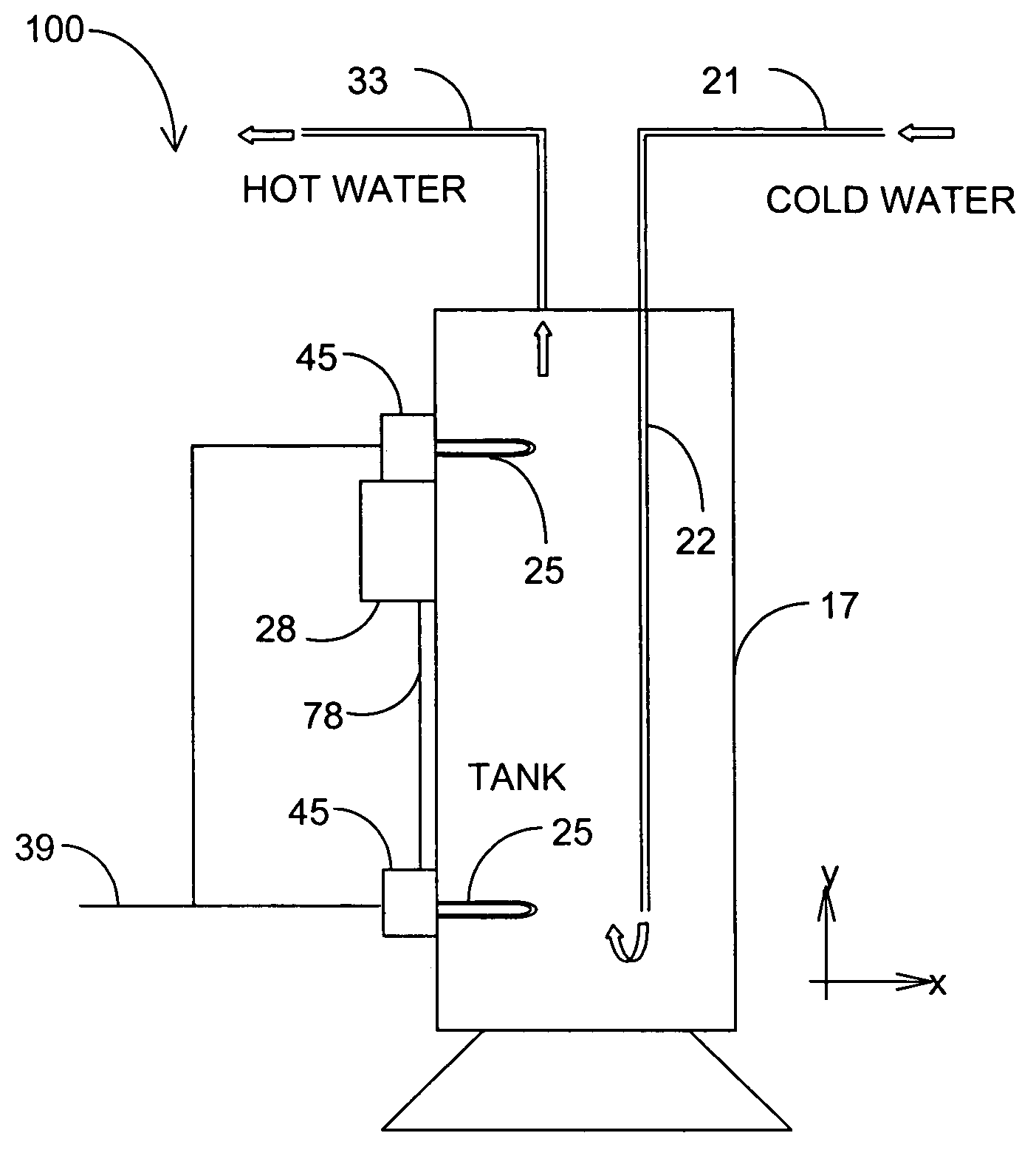
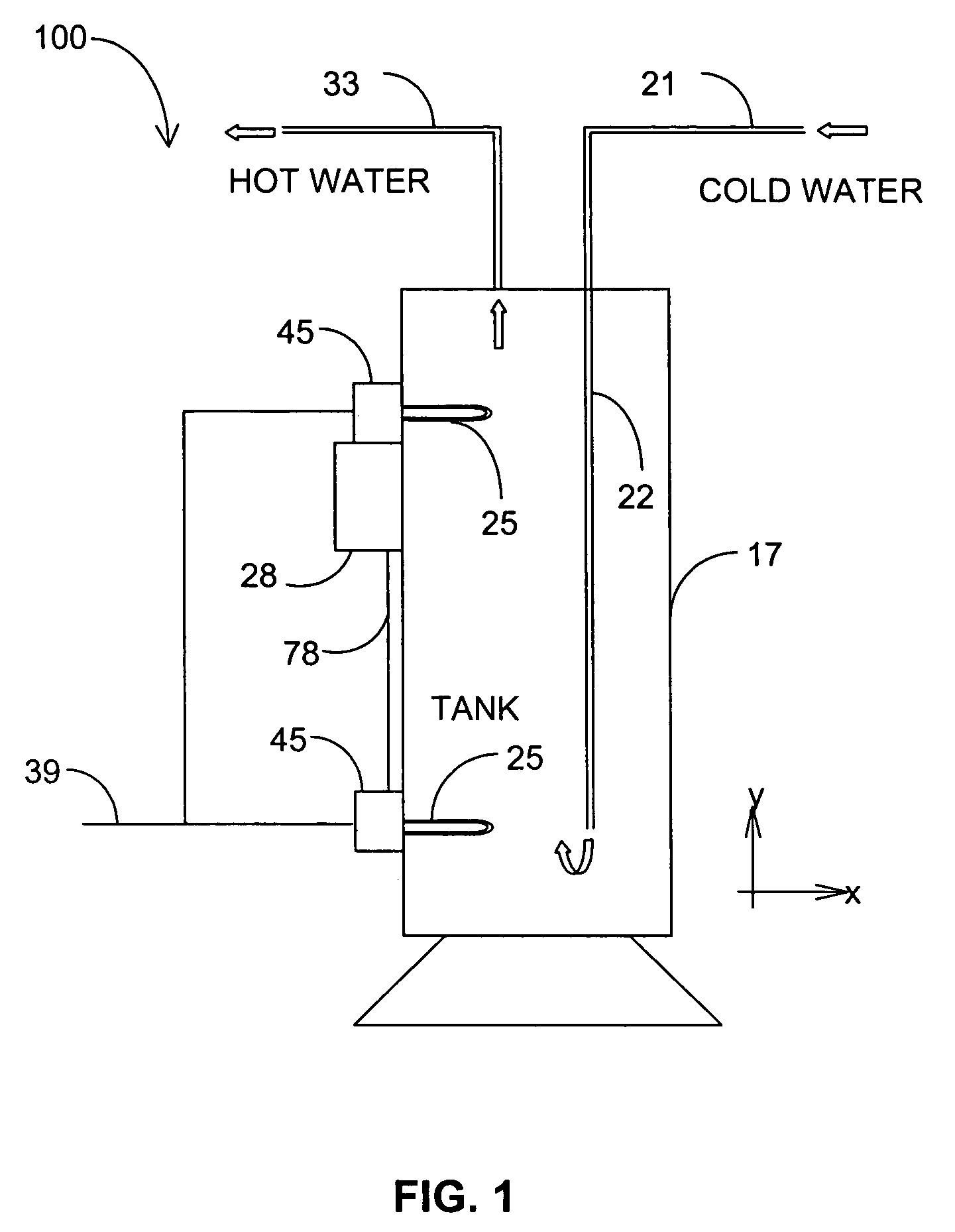
[0018]Generally, and as depicted in FIG. 1, a water heating system 100 has a controller 28 and at least one relay 45 for applying electrical power to at least one heating element 25 located within a water tank 17. Cold water is supplied to the water tank 17 by cold water pipe 21, and the cold water flows down (in the negative y direction) a filler tube 22 into the bottom section of the tank. Hot water is drawn (exits to a user) out of the upper section of the tank through hot water pipe 33. Note that FIG. 1 depicts two heating elements 25, an upper heating element (in the upper section or half of the tank 17) and a lower heating element (in the lower section or half of the tank 17). Other numbers and locations of heating ...


PUM


Abstract

A water heating system has a tank, a first heating element, a first temperature sensor, and a controller. The first heating element is mounted on the tank, and the controller is electrically coupled to the first temperature sensor. The controller is configured to detect a stacking condition based on the first temperature sensor and to disable the first heating element in response to detection of the stacking condition.

Description

CROSS REFERENCE TO RELATED APPLICATION[0001]This application claims priority to U.S. Provisional Application No. 60 / 584,401, entitled “Apparatus and Method for Fluid Temperature Control,” and filed on Jun. 30, 2004, which is incorporated herein by reference.FIELD OF THE DISCLOSURE[0002]The present disclosure generally relates to electrical hot water heaters. More particularly, the disclosure relates to a system and method for reducing stacking temperatures in a hot water heater.TECHNICAL BACKGROUND[0003]Devices such as hot water heaters, furnaces, and other appliances commonly include one or more heating elements that are controlled by a controller such as a thermostat. A heating element is activated (i.e., placed in an on-state) when heat is needed and deactivated (i.e., turned to an off-state) when heat is not required. The change of states normally occurs when a control signal turns a power relay on or off. Power relays have a pair of contacts capable of meeting the current requi...

Claims


Application Information

Patent Timeline
Patent Type & Authority Patents(United States)
IPC IPC(8): F22B1/28
CPCF24H9/2021F24H15/225F24H15/281F24H15/414F24H15/128F24H15/37
Inventor PHILLIPS, TERRY G.
Owner A O SMITH
Why Eureka
Try Eureka