Supercharge Your Innovation With Domain-Expert AI Agents!

Reset relief valve

a technology of reset valve and valve body, which is applied in the direction of valve operating means/releasing devices, functional valve types, transportation and packaging, etc., can solve the problems of weak components of the system, severe impact force on the piston and other elements of the valve, and ineffective fluid hydraulics using pumped or working fluid, etc., to achieve rapid flow path, strong crank assembly, and strong activation

Active Publication Date: 2006-10-10
RR VALVE
View PDF11 Cites 7 Cited by
  • Summary
  • Abstract
  • Description
  • Claims
  • Application Information

AI Technical Summary

Benefits of technology

"The invention is a reset relief valve that can be activated and re-set after being used. It uses hydraulic pressure to dampen the activation and provides a rapid flow path upon activation. The valve has a strengthened crank assembly to withstand high pressures and an improved piston for withstanding impact forces upon activation. The valve has a bonnet, stem bushing, and crank assembly for selectively engaging link members to move the piston into the first position. The technical effects of the invention are improved performance and reliability of the reset relief valve."

Problems solved by technology

In such systems, overpressure can damage valuable processing equipment or cause breakdown or rupture of weak components of the system.
In carrying out the rapid opening of the valve, movable port-blocking elements within the valve, such as a plug or piston, are subjected to high acceleration and velocity, resulting in severe impact forces being imposed on the piston and other elements of the valve when the moving member reached its limit of travel away from the port-blocking position.
Fluid hydraulics using the pumped or working fluid have not proven to be effective in that high impact forces often tear internal parts upon initial activation of the valve.
While the annular elastomeric cushion rings do provide effective initial shock attenuation, the rings, aided by the initial drop in pressure at the inlet port when the piston is moved from its blocking position, promote undesirable rebounding of the piston, which inhibits the free flow of fluid to the outlet port, and impose additional repetitive shock forces on the entire valve assembly.
Furthermore, the rebounding action attributed to the resilient rings often resulted in the relief valve resetting itself before release of the excess pressure, only to be triggered soon thereafter by the unrelieved pressure.
This opening and unintended resetting cycle could continue for a significant period of time until it was detected, and was a major contributor to wear and failure of the internal linkage mechanism and other components of the valve.
The various solutions in the prior art fail to provide a relief valve that can be manually reset after activation and that withstands the pressures commonly found in their application thereby avoiding damaging impacts on the valve and the need to replace the valve after it is activated.

Method used


Image

  • Reset relief valve
  • Reset relief valve
  • Reset relief valve

Examples


Embodiment Construction

[0027]Detailed descriptions of the preferred embodiment are provided herein. It is to be understood, however, that the present invention may be embodied in various forms. Therefore, specific details disclosed herein are not to be interpreted as limiting, but rather as a basis for the claims and as a representative basis for teaching one skilled in the art to employ the present invention in virtually any appropriately detailed system, structure or manner.

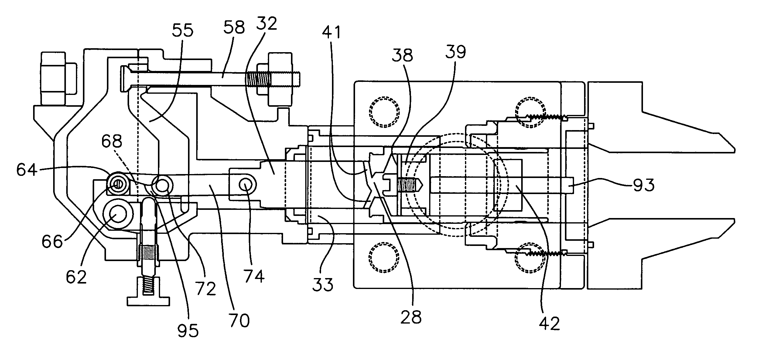
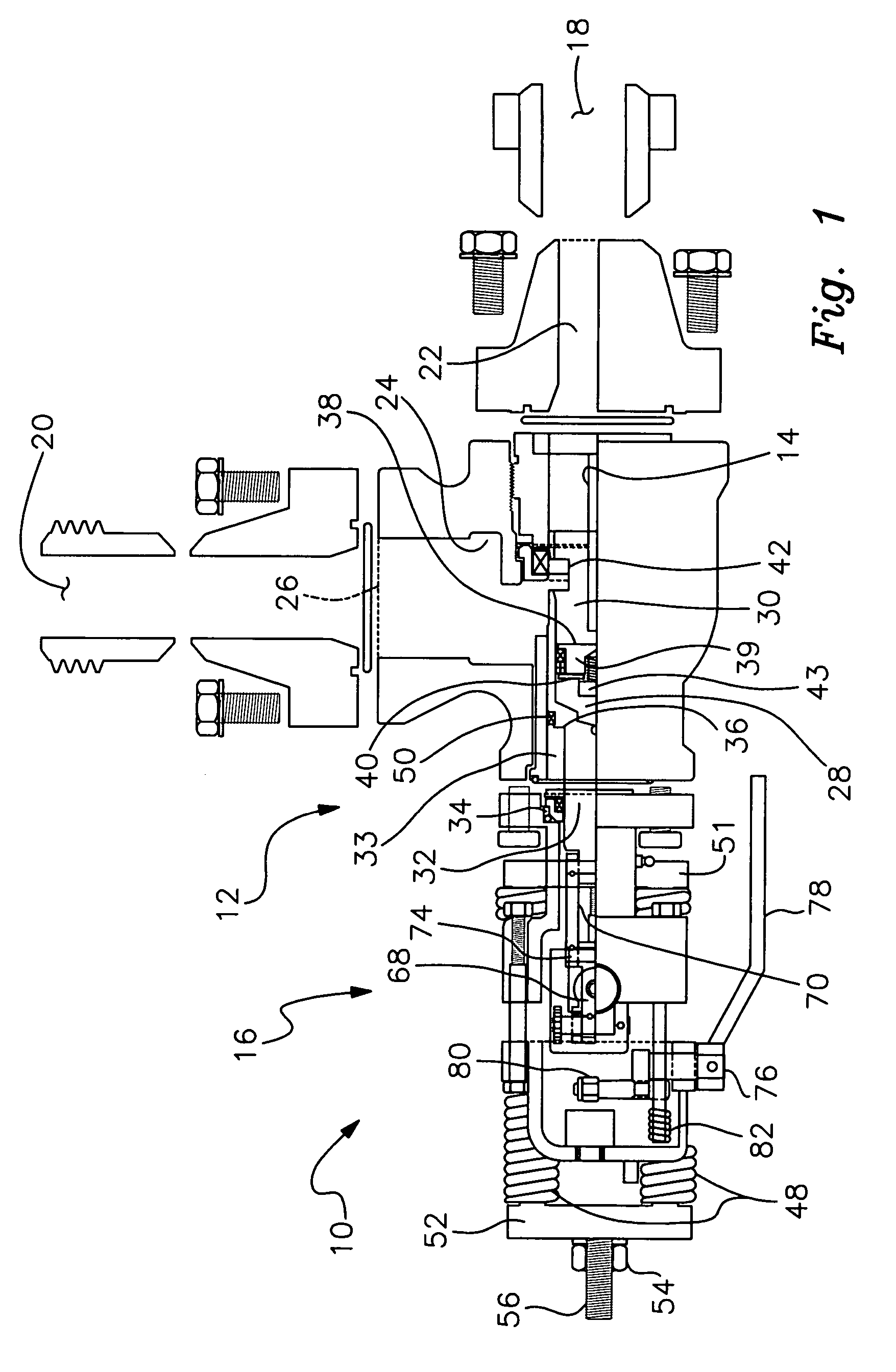
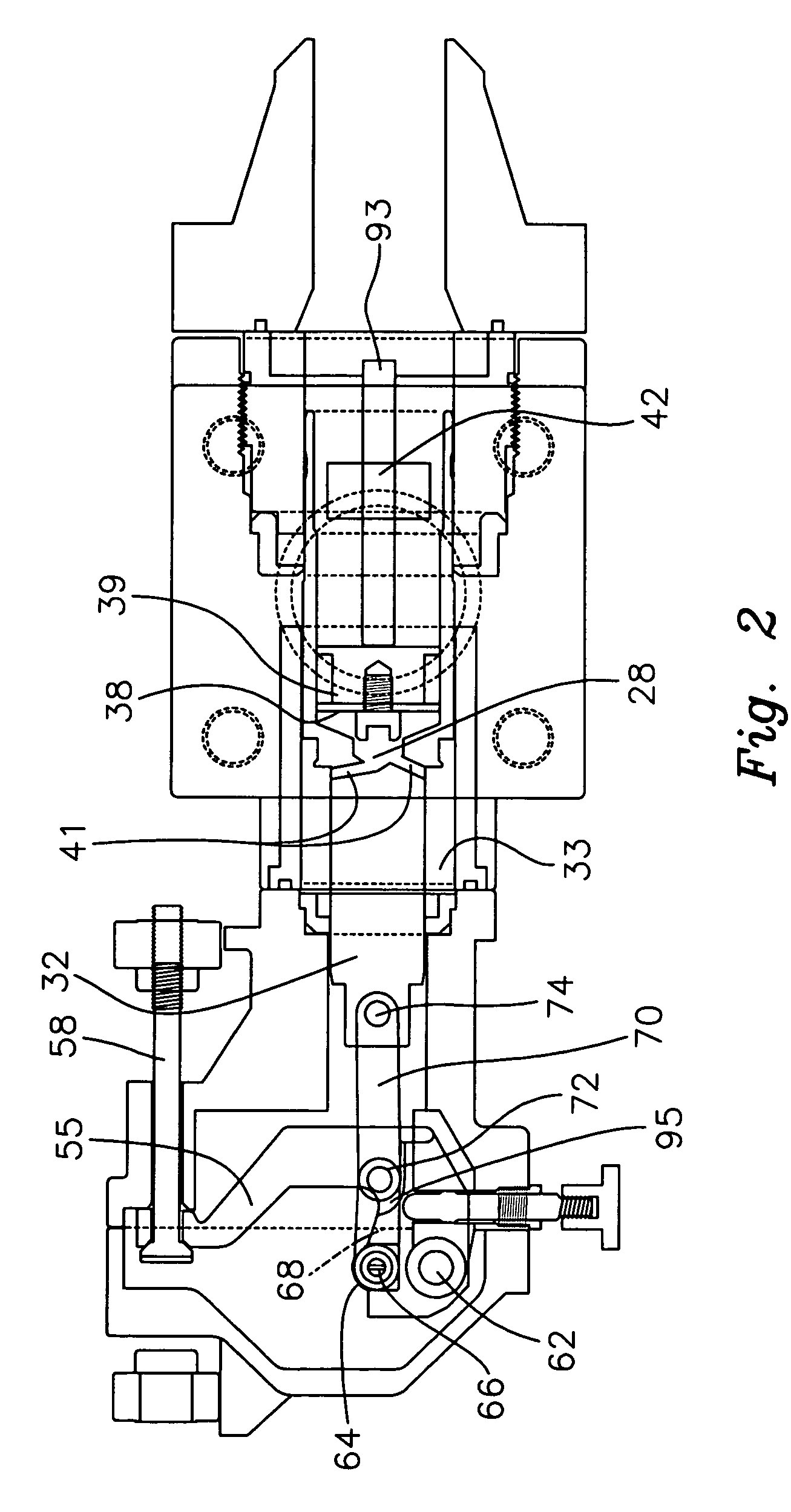
[0028]Turning now to FIG. 1, there is shown a partially exploded cross sectional view of the reset valve of the present invention. In the preferred embodiment of the present invention, shown in FIGS. 1–4, a pressure relief valve 10 has a body 12, a piston 14 movably disposed within the body 12, and a bonnet assembly 16. FIGS. 1–4 are shown in a horizontal orientation relative to the typical assembled vertical field position. References herein to an upward or downward movement or upper and lower positions refer to an orientation where...


PUM


Abstract

A reset relief valve with a body having an inlet port, an outlet port, and an interior wall partially defining an enclosed chamber, a piston disposed in the body and moveable between a first position at which the piston is disposed in fluid flow-blocking relationship between the inlet port and the outlet port of the body and a second position at which the piston is removed from that position, a piston having a head with opposed end surfaces one of which defines a portion of the enclosed chamber and at least one fluid flow passageway extending through the head and providing fluid communication between the enclosed chamber in the body, and a second chamber above a moveable disc in the piston. A preferred embodiment includes the crank assembly with cross bar support and a T-bar to prevent downward movement of the disc.

Description

CROSS REFERENCE TO RELATED APPLICATIONS[0001]This application is based on provisional application Ser. No. 60 / 445,690, filed on Feb. 7, 2003 and provisional application Ser. No. 60 / 467,640 filed May 3, 2003.STATEMENT REGARDING FEDERALLY SPONSORED RESEARCH OR DEVELOPMENT[0002]Not Applicable[0003]DESCRIPTION OF ATTACHED APPENDIX[0004]Not ApplicableBACKGROUND OF THE INVENTION[0005]This invention relates generally to the field of pressure relief valves and more specifically to a reset relief valve.[0006]Pressure relief valves are important components in certain fluid flow systems in which undesirable high pressure may occur. In such systems, overpressure can damage valuable processing equipment or cause breakdown or rupture of weak components of the system. It is desirable that when a pre-determined or pre-designated threshold pressure is exceeded, the pressure relief valve open very quickly, i.e., virtually instantaneously, to relieve system pressure. Pressure relief valves having this...

Claims


Application Information

Patent Timeline
Patent Type & Authority Patents(United States)
IPC IPC(8): F16K17/00F16K21/10F16K17/04F16K17/164F16K47/02
CPCF16K17/044F16K17/164F16K47/023Y10T137/7734Y10T137/7852Y10T137/7922
Inventor LAZZARA, GERARD S.COX, ERNEST F.
Owner RR VALVE
Features
  • R&D
  • Intellectual Property
  • Life Sciences
  • Materials
  • Tech Scout
  • Unparalleled Data Quality
  • Higher Quality Content
  • 60% Fewer Hallucinations
Learn More