Fire suppression system

a fire suppression system and fire suppression technology, applied in fire extinguishers, fire rescue, earthwork drilling and mining, etc., can solve the problems of not revealing an automatic actuation system, no device discloses an electrical and manual actuation system of fire suppression system,

Inactive Publication Date: 2006-10-10
MCLANE JR SAMUEL D
View PDF39 Cites 26 Cited by
  • Summary
  • Abstract
  • Description
  • Claims
  • Application Information

AI Technical Summary

Benefits of technology

[0011]In one embodiment, the piston body is a squib that contains an explosive material. The explosive material can be gun powder, plastic explosive or other types of explosive material. Ignition of the explosive material, in response to an electrical signal from the controller, results in creation of a high pressure gas that propels the piston outward. It is this propulsive effect that causes the piston to engage the ram and thereby actuate the piercing member.
[0012]In an alternate embodiment, the piston body is an electrically driven solenoid which causes the piston to move from a retracted position to an extended position thereby driving the ram and actuating the piercing member.

Problems solved by technology

And, while McLane and Doty taught that their fire suppression system was capable of manual, electrical, pneumatic or thermal activation, or of activation by any combination of those methods, they did not disclose a system for providing electrical and manual actuation of the fire suppression system.
None of these devices disclose an automatic actuation system that can be readily, easily and efficiently adapted to the actuation mechanism of the '635 patent.

Method used


Image

  • Fire suppression system
  • Fire suppression system
  • Fire suppression system

Examples


Embodiment Construction

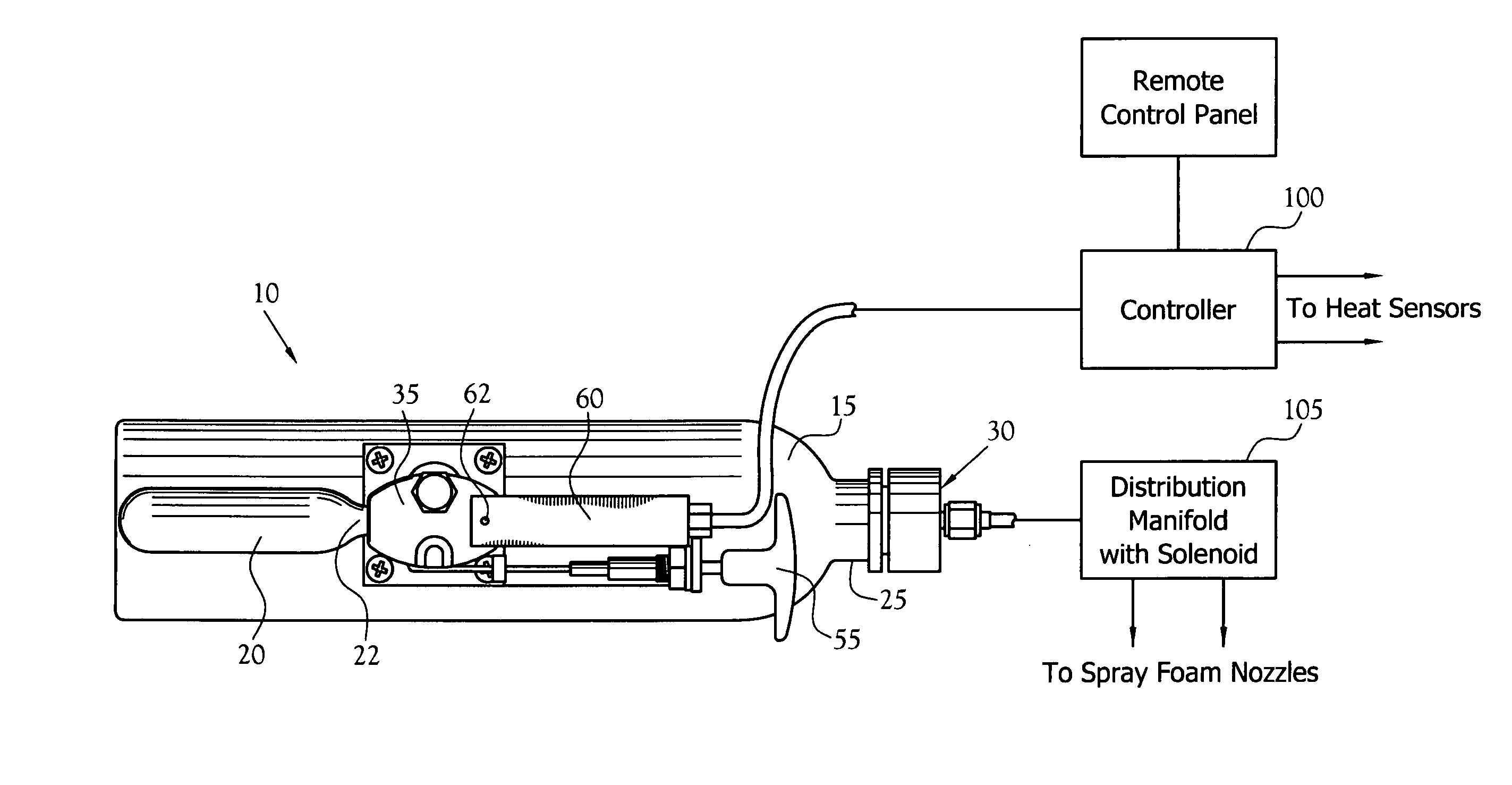
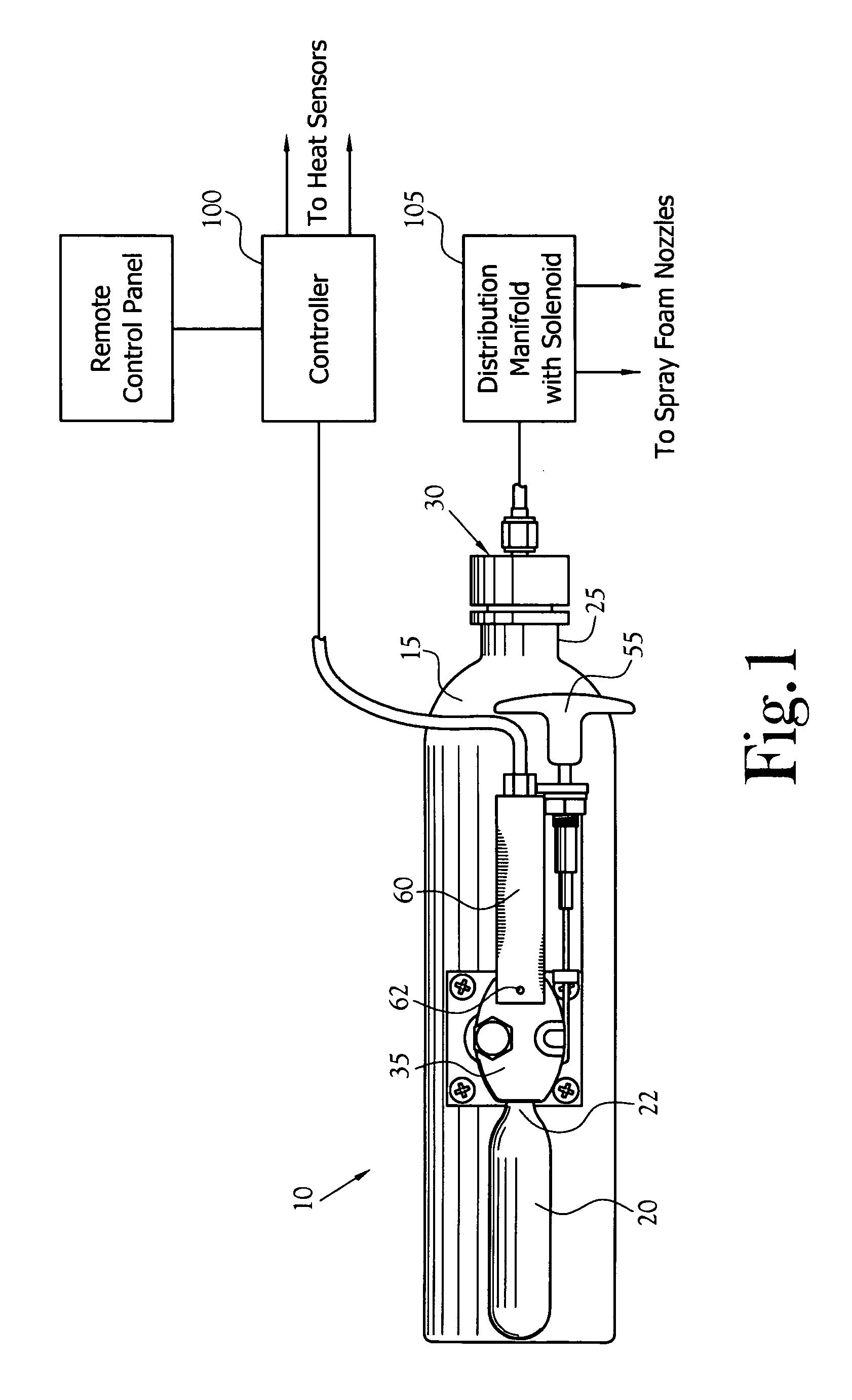
[0025]An improved fire suppression system, constructed in accordance with the present invention is illustrated generally as 10 in the figures. As stated above, the present invention is an improvement to the fire suppression system disclosed in the '635 patent. The improved fire suppression system includes a first canister 15 containing a fire suppressing agent. The first canister 15 includes an inlet (not shown) in fluid communication with a second canister 20 containing an agitating and pressurizing agent. The first canister also includes an outlet 25 defining a neck for receiving a discharge mechanism 30. In one embodiment, the second canister 20 is a CO2 cylinder, as is commonly used with CO2 energized projectile firing guns, having an outlet 22 with a pierceable seal (not shown) disposed about the outlet 25. The second canister 20 is received by an actuating mechanism 35 for establishing a fluid communication between the first canister 15 and the second canister 20. The actuatin...


PUM


Abstract

A vehicular and marine fire suppression system for detecting and suppressing and quenching fires. The vehicular and marine fire suppression system including a first canister, a second canister and an actuation mechanism. The first canister houses a fire suppressing agent and is in fluid communication with a manifold assembly for providing delivery of the fire suppression agent from the first canister to the area to be protected by the fire suppression system. The second canister contains a pressurizing / agitation agent and is in fluid communication with the first canister via a valved actuator assembly. The second canister includes a threaded neck defining an outlet and a pierceable seal disposed about the outlet. The actuator assembly includes a piercing member for rupturing the pierceable seal of the second canister. The piercing member is in active engagement with a piston carried by a squib. Ignition of an explosive agent within the squib is used to drive the piston to an extended position thus causing the piercing member to rupture the pierceable seal of the first canister. State-of-the-art heat / smoke detection circuitry and a programmable logic circuit are provided for detecting a fire and delivering an electrical signal to the squib. A handle member and a linkage in operative engagement with the piercing member is provided for manual actuation of the fire suppression system. Alternatively, an electrically actuated solenoid could be used to actuate the piercing member.

Description

CROSS-REFERENCE TO RELATED APPLICATIONS[0001]Not ApplicableSTATEMENT REGARDING FEDERALLY SPONSORED RESEARCH OR DEVELOPMENT[0002]Not ApplicableBACKGROUND OF THE INVENTION[0003]1. Field of Invention[0004]This invention relates to the field of fire suppression systems. More particularly, this invention relates to fire suppression systems that suppress fires originating in vehicular and marine systems and particularly in recreational vehicles.[0005]2. Description of the Related Art[0006]In the fields of vehicular and marine fire suppression, it is well known that effectiveness and efficiency of operation are critical factors in containing and quenching a fire. The importance of such factors is enhanced when considering fires within marine and automotive racing compartments, as well as in recreational vehicles, where escape from an engulfed vehicle is typically unlikely or where there is the potential for a wider scope of injury such as in a marina or a multi-car collision. In U.S. Pat. ...

Claims


Application Information

Patent Timeline
Patent Type & Authority Patents(United States)
IPC IPC(8): A62C35/00A62C3/07
CPCA62C3/07Y10S169/03
Inventor MCLANE, JR., SAMUEL D.
Owner MCLANE JR SAMUEL D
Why Eureka
Try Eureka