Retort system

a retort system and dental restoration technology, applied in the direction of muffle furnaces, impression caps, foundry moulding apparatus, etc., can solve problems such as downgrades in stability

Active Publication Date: 2006-10-10
IVOCLAR VIVADENT AG
View PDF12 Cites 9 Cited by
  • Summary
  • Abstract
  • Description
  • Claims
  • Application Information

AI Technical Summary

Benefits of technology

[0015]In contrast to the above-noted shortcomings, the present invention provides a solution to the challenge of

Problems solved by technology

Due to the enlarged thickness, the thus-deployed ceramic blank can, at the same tim

Method used


Image

  • Retort system
  • Retort system
  • Retort system

Examples


Embodiment Construction

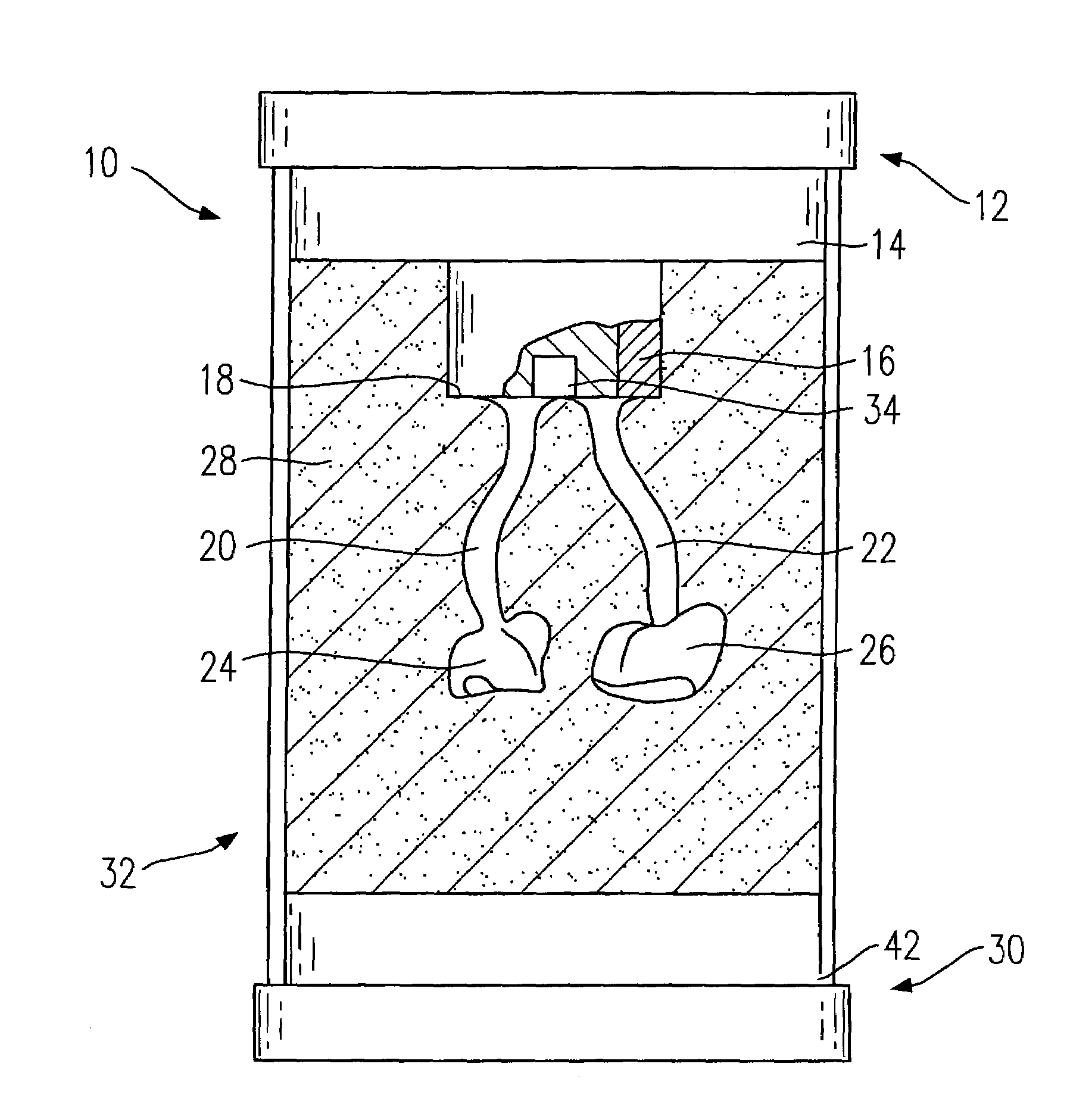
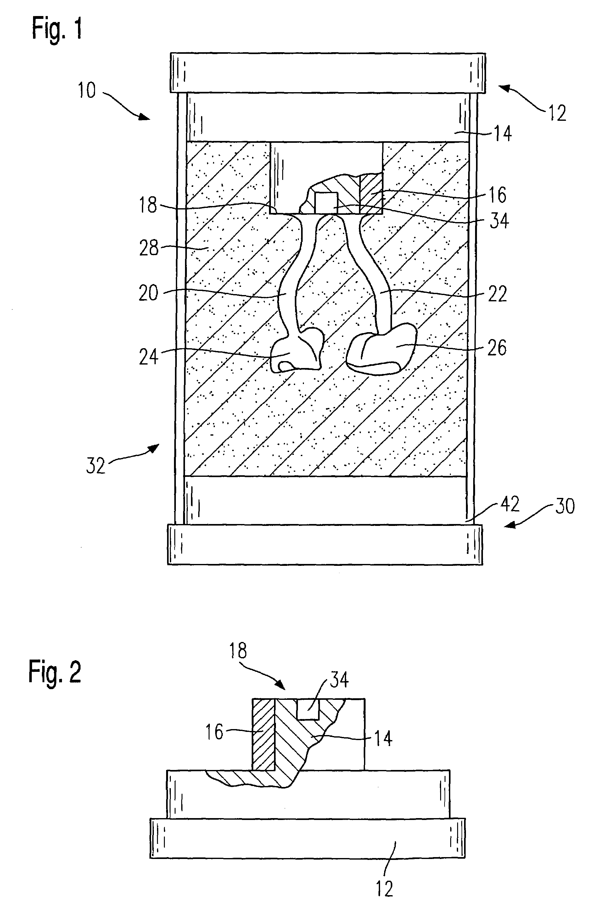
[0039]FIG. 1 shows a first embodiment of the inventive retort system 10 which comprises a retort base 12 from which a retort cylinder 14 extends downwardly, as viewed in the position shown in FIG. 1.

[0040]In accordance with the present invention, the side of the retort cylinder 14 is encircled by a charging body 16, whereby, in the illustrated embodiment shown in FIG. 1, the charging body 16 is annularly shaped and has a wall thickness of approximately one-half the radius of the retort cylinder.

[0041]The retort cylinder 14 comprises a growth surface 18 on its lower region on the end face thereof turned away from the retort base 12. At least one support arm comprised of wax is mounted on the growth surface 18, whereby, in the illustrated embodiment, two support arms 20 and 22 are configured. Wax models 24 and 26 are provided somewhat centrally in the retort system 10 on the other ends of the support arms 20 and 22, the wax models corresponding in their form to the dental restorations...


PUM

PropertyMeasurementUnit
Thicknessaaaaaaaaaa
Massaaaaaaaaaa
Coloraaaaaaaaaa

Abstract

A method for producing dental restoration components includes filling a retort cylinder of a retort system with a forming mass, the retort cylinder being at least partially encircled by a charging body, and hardening the forming mass. After the hardening of the forming mass, the retort cylinder and the charging body are removed from the forming mass, thereby leaving behind a retort. Thereafter, with the assistance of a press blank apparatus, a press blank having an outer contour substantially corresponding to the outer contour of the charging body is pressed into the retort.

Description

CROSS-REFERENCE TO RELATED APPLICATIONS[0001]This application claims foreign priority benefits under 35 U.S.C. §119(a)–(d) from German patent application ser. no. P 102 57 208.9 filed Dec. 6, 2002.TECHNICAL FIELD[0002]The present invention relates to a method for producing dental restoration components, a retort system, and a press blank, all especially for use in connection with dental ovens.BACKGROUND OF THE INVENTION[0003]Retort ovens have been known for a long time such as, for example, as is disclosed in DE-0S 198 44 136. In retort ovens of this type, a wax model of a dental restoration is embedded in a cast bed in order to produce a negative form. The retort is then heated and warmed so that the model composed of wax melts and there remains the temperature resistant negative form or mold in readiness for the introduction thereinto of a to-be-pressed ceramic mass.[0004]Dental restoration can demand decidedly different forms and volumes. Correspondingly, at the same time several...

Claims


Application Information

Patent Timeline
IPC IPC(8): A61C13/20A61C13/00F27B5/10F27B17/02
CPCA61C13/20F27B5/10F27B17/025Y10S164/04
Inventor FOSER, HANSPETERSTAMPFER, THOMAS
Owner IVOCLAR VIVADENT AG
Why Eureka
Try Eureka