Ionized air flow discharge type non-dusting ionizer

Inactive Publication Date: 2006-10-24
TECHNO RYOWA +2
View PDF32 Cites 13 Cited by
  • Summary
  • Abstract
  • Description
  • Claims
  • Application Information

AI Technical Summary

Benefits of technology

[0013]In the ionized gas current emission type dust-free ionizer of the present invention, which has the construction described above, since a corona discharge that might be a cause of ignition is not used as the ionization source, the ignition of combustible substances such as organic solvents or the like can be prevented. Furthermore, since the ionization source and control device are disposed so that these parts are separated from each other, and since the chamber is formed in a cylindrical shape and is ad

Problems solved by technology

In recent years, in explosion-proof facilities such as facilities where hazardous substances are handled or the like, clogging during the air feeding of combustible powders and clogging of sieves, as well as static charge build-up and discharge in the interiors of agitating tanks for organic solvents or the like whose inside surfaces are coated with Teflon, have become problems.
In the case of such de-charging methods, however, the initial costs and running costs of auxiliary facilities such as gas supply and exhaust facilities or the like are high, so that such methods are not desirable.
However, semiconductor and liquid crystal manufacturing devices have become progressively smaller over the years, and in the case of conventional ionizers, it has become difficult to ensure an optimal installation space.
Specifically, in the case of corona discharge type ionizers commonly used i

Method used


Image

  • Ionized air flow discharge type non-dusting ionizer
  • Ionized air flow discharge type non-dusting ionizer
  • Ionized air flow discharge type non-dusting ionizer

Examples


first embodiment

(1) FIRST EMBODIMENT

(1-1) Construction

(1-1-1) Overall Construction

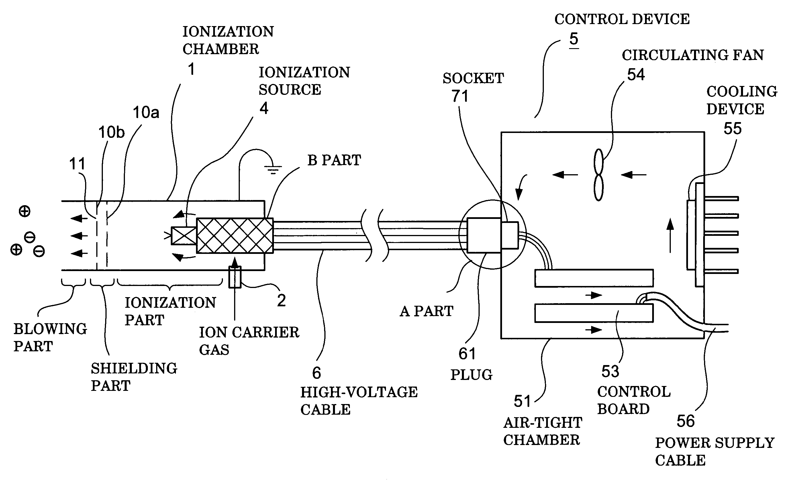
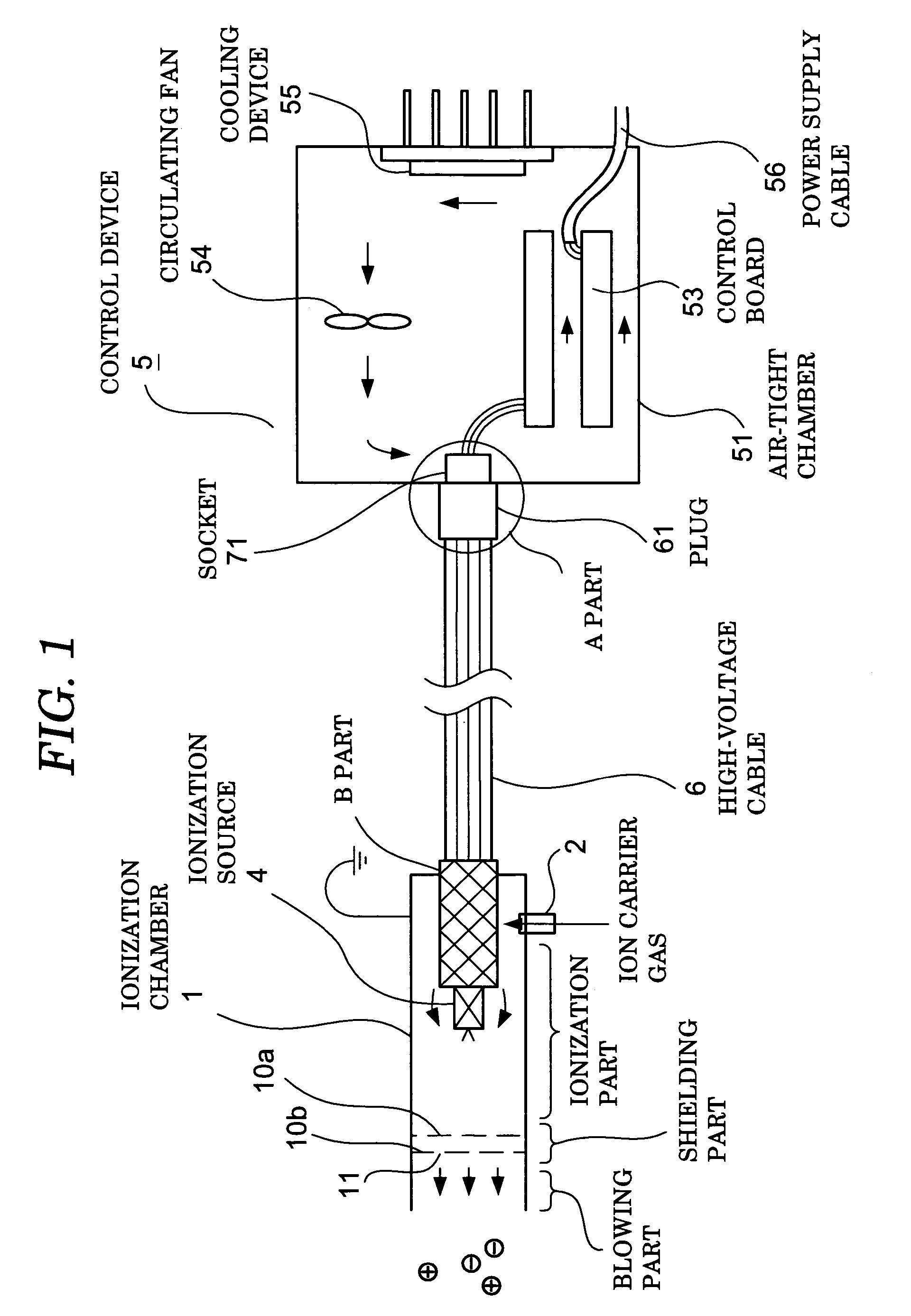
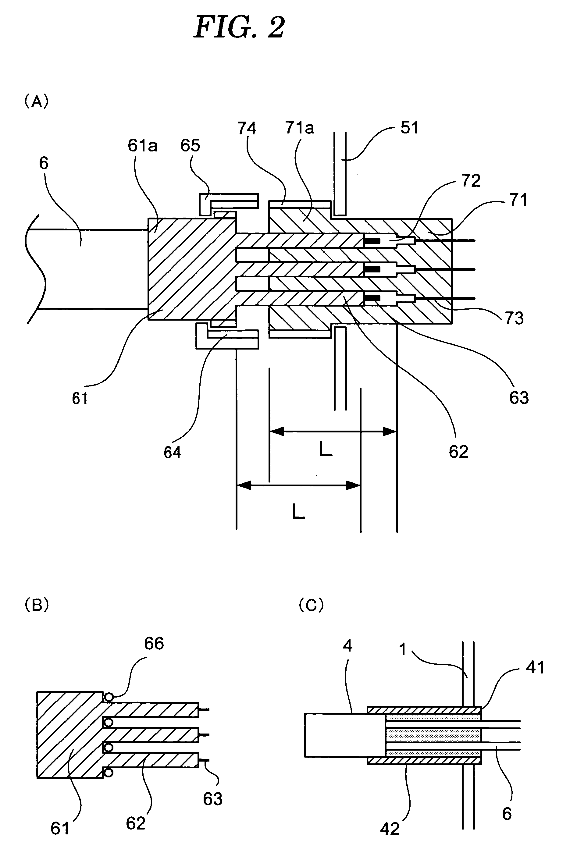
[0029]FIG. 1 is a model diagram which shows the overall construction of the ionized gas current emission type dust-free ionizer of the present embodiment. In the same figure, 1 indicates a cylindrical ionization chamber (hereafter referred to as a “chamber”); this chamber is constructed from a metal such as aluminum, stainless steel or the like, or a resin such as polyvinyl chloride or the like. Furthermore, in terms of main parts, this chamber 1 is constructed from an ionization part, a shielding part and a blowing part. An ionization source 4 is disposed in the interior of the chamber 1; this ionization source 4 is connected via a high-voltage cable 6 to a control device 5 which controls the quantity of ions generated by the ionization source 4.

[0030]Furthermore, the ionized gas current emission type dust-free ionizer of the present invention has characterizing features in the construction of the control device 5, t...

second embodiment

(2) SECOND EMBODIMENT

[0057]The present embodiment is a modification in which the construction of the shielding part of the abovementioned first embodiment is altered.

[0058]In the present embodiment, as is shown in FIG. 3, the shielding part of the chamber 1 is constructed from two semi-circular partition walls 7, 7; these partition walls 7, 7 are alternately formed on the upper part and lower part of the chamber 1 so that a fixed gap is left. Specifically, in cases where the ionization source 4 is a soft X-ray generating part or low-energy electron beam generating part, the system is adapted so that the linearly advancing soft X-rays or electron beam electrons strike the partition walls 7, 7, thus providing a construction in which shielding is provided so that these soft X-rays or electrons do not leak to the outside. Furthermore, in cases where the ionization source 4 is an ultraviolet radiation generating part, this shielding part is unnecessary. The remaining construction is the ...

third embodiment

(3) THIRD EMBODIMENT

[0060]The present embodiment is a modification in which the construction of the blowing part of the abovementioned first embodiment is altered. Furthermore, it goes without saying that the blowing part of the present embodiment can also be applied to the abovementioned second embodiment.

[0061]In the present embodiment, as is shown in FIG. 4, a nozzle 20 which is used to cause jetting of the ionized gas current is disposed on the downstream side of the shielding part of the chamber 1. For example, a nozzle 216, flat nozzle 920, air curtain 302–306, air knife 392–396 or the like manufactured by SILVENT Co. can be used as the abovementioned nozzle 20.

[0062]In the ionized gas current emission type dust-free ionizer of the present embodiment, which has the construction described above, the same effects and merits as those of the abovementioned first embodiment or second embodiment can be obtained; moreover, since a nozzle 20 which has a desired shape and size is attac...


PUM


Abstract

The ionizer of the present invention comprises a chamber which has an ionization part that ionizes a portion of an ion carrier gas that is supplied to the interior of this chamber, and a blowing part which feeds the ion carrier gas toward a charged body. The ionization part is constructed from an ionization source which is contained in the chamber, and a control device which is connected with this ionization source via a high-voltage cable. Either the generating part of a soft X-ray generating device, the generating part of a low-energy electron beam generating device or the generating part of an ultraviolet radiation generating device is used as the ionization source. The control device, the connecting part between the control device and the high-voltage cable and the connecting part between the ionization source and the high-voltage cable are formed with an explosion-proof structure.

Description

TECHNICAL FIELD[0001]The present invention relates to an ionizer which is used to eliminate static electricity, and more particularly relates to an ionized gas current emission type dust-free ionizer which is an ionizer of a type that emits an ionized gas current toward the object of static electricity removal, and which can be used in explosion-proof facilities and equipment.BACKGROUND ART[0002]In recent years, in explosion-proof facilities such as facilities where hazardous substances are handled or the like, clogging during the air feeding of combustible powders and clogging of sieves, as well as static charge build-up and discharge in the interiors of agitating tanks for organic solvents or the like whose inside surfaces are coated with Teflon, have become problems. Conventionally, in the case of static charge build-up and discharge inside such agitating tanks, the ignition of the organic solvents has been prevented by purging the air from the tanks with N2 gas, so that oxygen t...

Claims


Application Information

Patent Timeline
IPC IPC(8): H05F3/06H01T23/00H05K9/00
CPCH01T23/00H05F3/06
Inventor MIZUNO, AKIRASUGITA, AKIOSUZUKI, MASANORISATO, TOMOKATSUHINO, TOSHIHIKOTOGARI, HARUYUKI
Owner TECHNO RYOWA
Why Eureka
Try Eureka