Screen Saver Sub

a screen saver and sub-system technology, applied in the field of downhole completions, can solve the problems of reducing the available inside diameter, preventing the passage of tools, and reducing the pressure generated while fracturing the formation at that point, so as to reduce the internal diameter, prevent the collapse pressure, and increase the collapse strength

Inactive Publication Date: 2008-11-13
BAKER HUGHES INC
View PDF9 Cites 3 Cited by
  • Summary
  • Abstract
  • Description
  • Claims
  • Application Information

AI Technical Summary

Benefits of technology

[0005]A transition piece is provided near an end of a screen assembly to allow transition from a low collapse resistant pipe under the screen sections to a higher collapse strength pipe between the top of the screen and below the isolation packer. When a screen out occurs, the heavier wall and / or higher material strength pipe can handle the higher pressures that are applied to the annular space and to the tubular trying to collapse it. The screen portion can still be built with thinner wall and / or lower strength pipe as the screen out condition protects that pipe from collapse pressure because the fully gravel packed annular space keeps the surface applied pump pressure from exerting a collapse force on the base pipe under the screen. The internal diameter under the screen does not have to be reduced because the heavy wall pipe is not provided there. Above the screen, a heavy wall pipe can be provided because the absence of the screen layer allows more room for a larger pipe with thicker wall without decrease in internal diameter as compared to under the screen. An opening or openings in the adapter prevent collapse pressure from affecting the blank pipe above the screen. The opening or openings can be covered with a screen or shaped to hold the proppant back.

Problems solved by technology

There is a risk that the pressures generated while fracturing the formation at that point could be higher than the collapse strength of the tubular.
The problem with that approach is that it is expensive and when the well space is limited, the provision of thick wall pipe simply results in a decrease in the available inside diameter.
That inside diameter constriction could impede the passage of tools through the screen for a subsequent operation and production from the well.

Method used


Image

  • Screen Saver Sub
  • Screen Saver Sub

Examples


Embodiment Construction

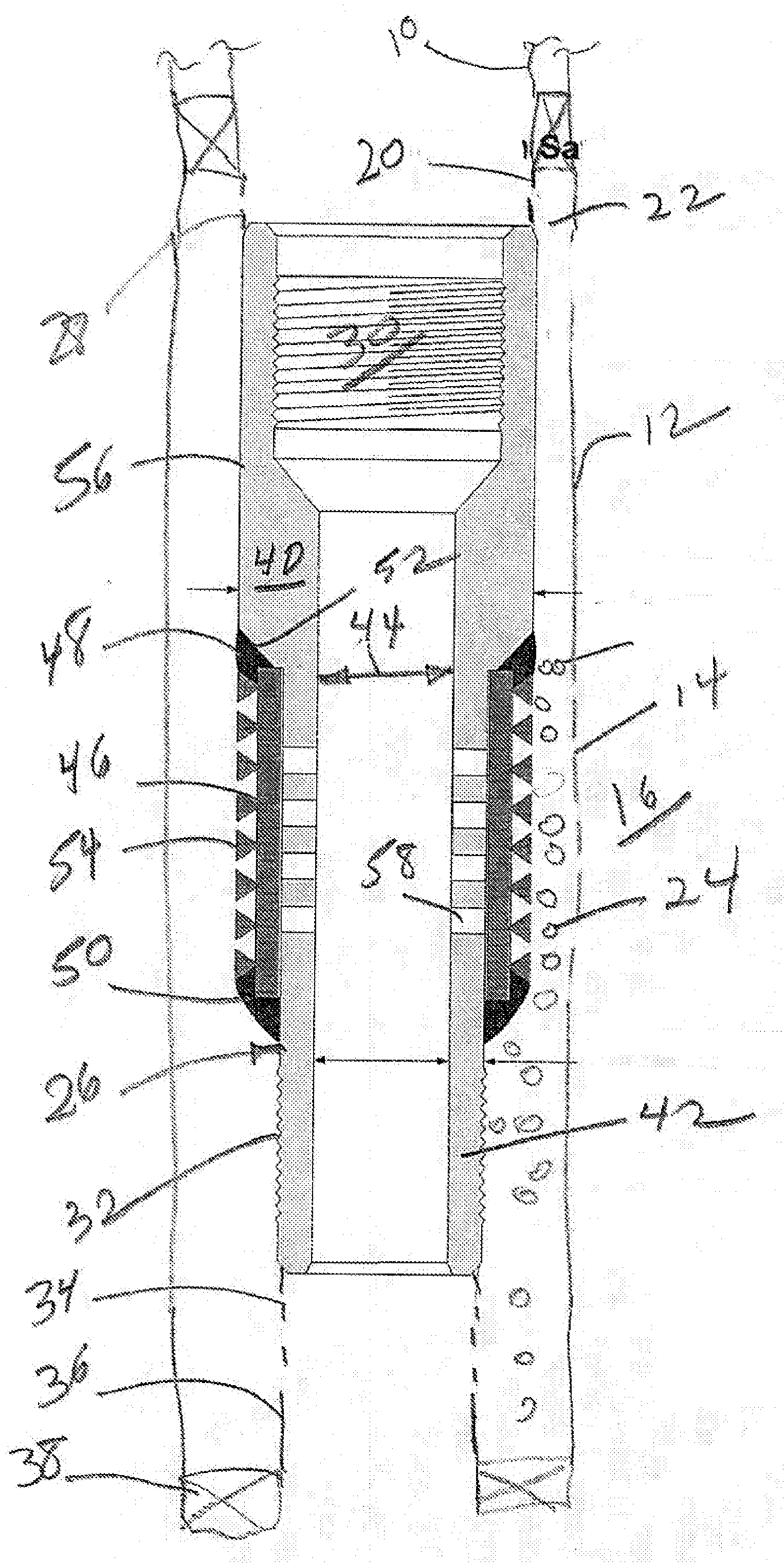
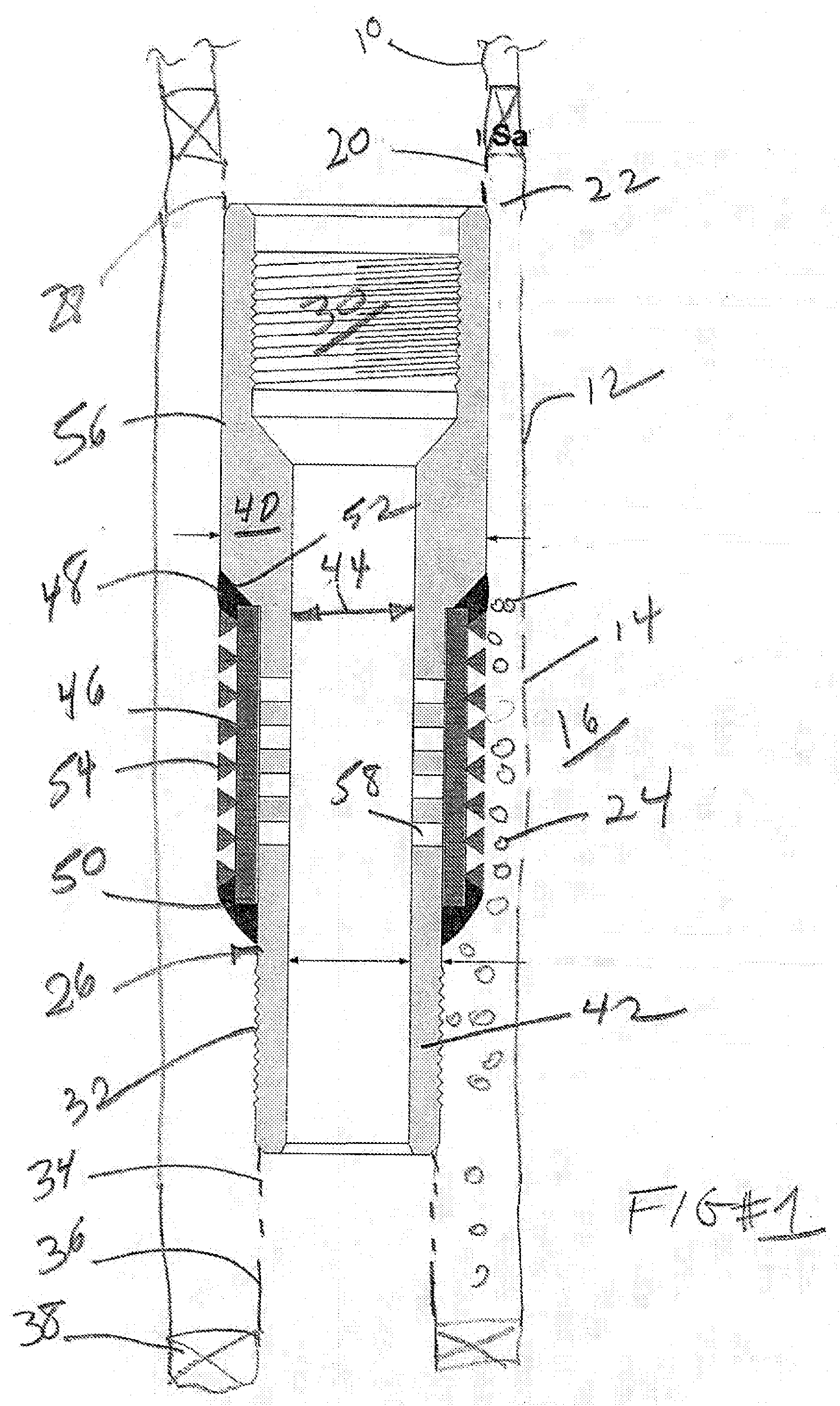
[0007]FIG. 1 shows a tubing string 10 that can extend from the surface into casing 12 for example or into open hole. Casing 12 can have slots or perforations 14 made by a gun, for example, for access to a formation 16. Tubing string 10 extends through a packer 18 and then goes to a crossover 20. Crossover 20 provides access to the annular space 22 for the gravel slurry 24. The sub 26 that is the present invention is mounted below some blank pipe 28 that extends from the crossover 20 (shown schematically).

[0008]Sub 26 has a top thread 30 for connection to blank pipe 28. It has a lower thread 32 for connection to one or more screen sections 34. Below screen sections 34 is an adapter 36 to allow connection to or sealing into lower packer 38. The wall thickness 40 in sub 26 is greater than the wall thickness 42 but without reduction in internal diameter 44.

[0009]A screen assembly 46 which can be any number of known screen designs can be attached in a variety of ways to sub 26 such as by...


PUM


Abstract

A transition piece is provided near an end of a screen assembly to allow transition from a lighter weight and collapse resistant pipe under the screen sections to a heavier wall and higher collapse strength pipe between the top of the screen and the isolation packer. When a screen out occurs, the heavier wall pipe can handle the new pressures that are applied to the formation and to the tubular to try to collapse it. The screen portion can still be built with thinner wall pipe as the screen out condition protects that pipe from collapse pressure because the fully gravel packed annular space keeps the surface applied pump pressure from exerting a collapse force on the base pipe under the screen. The internal diameter under the screen does not have to be reduced because the heavy wall pipe is not provided there. Above the screen, a heavy wall pipe can be provided because the absence of the screen layer allows more room for a larger pipe with thicker wall without decrease in internal diameter as compared to under the screen.

Description

FIELD OF THE INVENTION[0001]The field of the invention is downhole completions and more particularly completions involving fracturing and gravel packing with the screen in the well.BACKGROUND OF THE INVENTION[0002]Completions can involve insertion of section of screen in an isolated zone that is sealed off with packers. The screen assembly is sealed into the lower packer and generally has a section of blank pipe above the screen portion connected to the bottom of the upper packer at either end of the zone that is isolated for subsequent production. When the completion plan calls for fracturing and gravel packing the procedure is to deliver the proppant in viscous slurry through the top packer. From there the slurry goes through a crossover to get into the annular space around the screen. As long as some portion of the screen is uncovered the pressure of the viscous carrier fluid can be communicated to the formation in a fairly predictable manner. Once the annular space fills high en...

Claims


Application Information

Patent Timeline
Patent Type & Authority Applications(United States)
IPC IPC(8): E21B43/08
CPCE21B43/088E21B43/08E21B43/04
Inventor CORBETT, THOMAS G.BAYNE, CHRISTIAN F.
Owner BAKER HUGHES INC
Why Eureka
Try Eureka