Faucet seal and spring tool

a technology of spring tool and seal, which is applied in the direction of metal-working tools, metal-working equipment, metal-working equipment, etc., can solve the problems of fixing leakage, seal cracking or breaking, and sealing may be necessary, so as to reduce the internal diameter

Inactive Publication Date: 2005-09-15
BATES WENDELL P
View PDF3 Cites 2 Cited by
  • Summary
  • Abstract
  • Description
  • Claims
  • Application Information

AI Technical Summary

Benefits of technology

[0011] A faucet and spring tool utilized to remove and replace the seal and spring from a faucet valve assembly. The device consists of a cylindrical, hollow external housing having upper and lower ends and a cylindrical guide having upper and lower ends and designed to be removably disposed within the external housing such that the lower end of the guide does not extend beyond the lower end of the external housing in a resting position. A cap is removably attachable to the upper end of the cylindrical guide such that the cap extends beyond the upper end of the external housing in a resting position. A compression spring having upper and lower ends is disposed within the upper end of the external housing such that depression of the cap causes compression of the spring which further causes the lower end of the cylindrical guide to extend beyond the lower end of the external housing. The lower end of the compression spring is held in place by an area of reduced internal diameter in the external housing. The cylindrical guide includes a lip which interacts with an area of reduced internal diameter in the external housing to prevent the cylindrical guide from sliding past a predetermined location. The cap is either pressure fit to or threaded onto the upper end of the cylindrical guide. The external housing includes stationary grip handles which are preferably formed integrally with the external housing and which preferably are curved to accept a user's fingers. The external housing, the cap and the cylindrical guide are preferably formed from a water resistant or waterproof material, such as a plastic, composite or a thermoplastic.

Problems solved by technology

If the seal structure fails, the fixture will leak and replacement of the seal is necessary.
The rubber seal may crack or break or the springs may lose their memory and fail to perform as intended, causing the faucet to leak.
Replacement of this seal normally resolves the leak but is difficult because of the small size of the seal structure and the small area in which the structure is located.
The use of screwdrivers and other long tools is common in the industry since the location of the worn seal structure is not easily accessible.
Additionally, this repair does not lend itself to completion by hand since there is not sufficient room in most faucets for an adult's fingers.
This design is complicated and difficult to use.

Method used


Image

  • Faucet seal and spring tool
  • Faucet seal and spring tool
  • Faucet seal and spring tool

Examples


Embodiment Construction

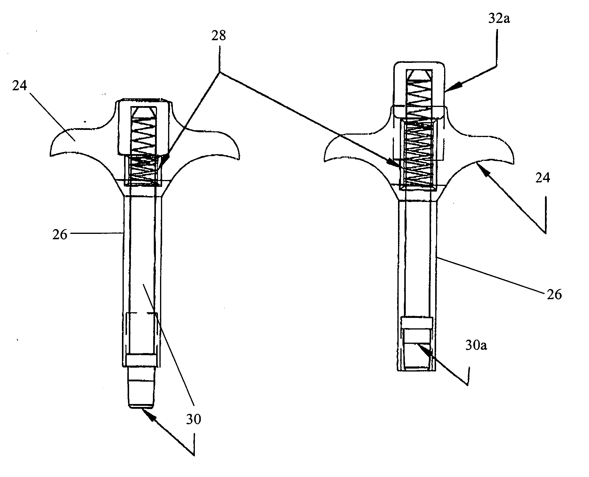
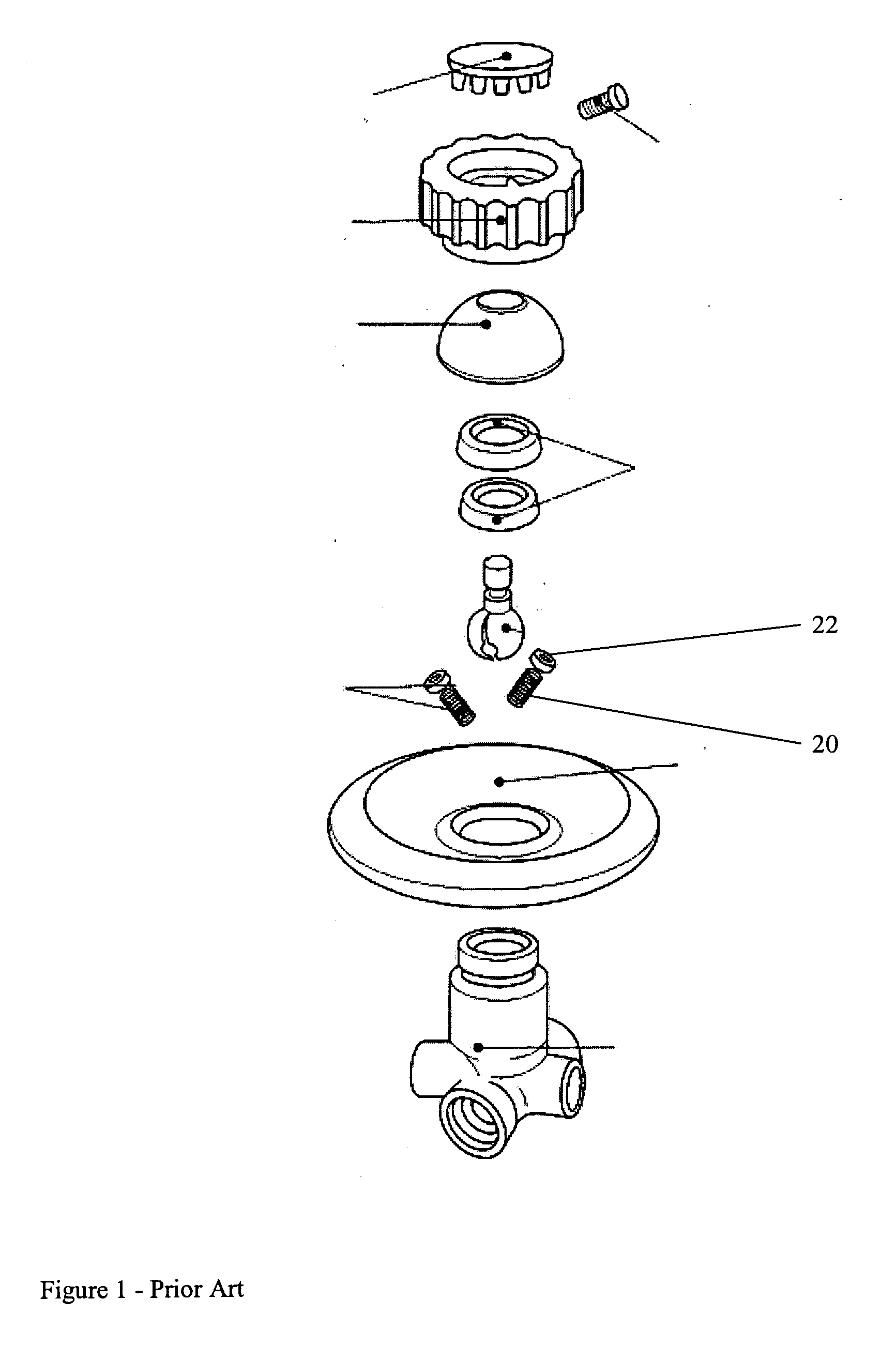
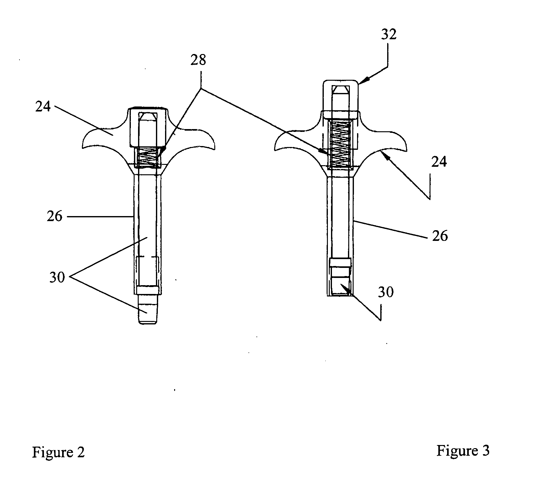
[0037] The spring 20 and seal 22, shown in FIG. 1, are located in a predetermined location in the faucet that is difficult to remove and replace without great difficulty because of the small size of the spring 20 and seal 22 and the constrictions of the location. This is most notable in a bathtub faucet when the seal 20 and spring 22 require replacement. The faucet assembly is usually located in a vertical position and keeping the seal 22 and spring 20 in place while removing or inserting them is challenging. The present invention allows the old seal 22 and spring 20 to be removed together and replaced with a new seal 22 and spring 20 in unison while maintaining correct location placement.

[0038] A standard faucet valve assembly has a valve body with a main bore and a counterbore inlet passageway leading from a supply of water. The counterbore holds a tubular seal (seal 22 and spring 20) element in the inlet passageway of the valve body. The present invention enables the user to rem...


PUM

PropertyMeasurementUnit
internal diameteraaaaaaaaaa
pressureaaaaaaaaaa
water resistantaaaaaaaaaa

Abstract

A simplified tool for removing and inserting a plumbing fixture seal, particularly for use with ball type faucets using a rubber seal engaged by a cylindrical compression spring. The tool comprises an outer housing; an inner member having a tapered end designed to frictionally engage the seal and spring, said member being reciprocally disposed within the outer housing, said inner member being retracted inside the outer housing by a retraction spring; and a means for extending the tapered end of the inner member beyond the end of the outer housing sufficient to engage the seal and spring.

Description

CROSS REFERENCE TO RELATED APPLICATION [0001] The present application claims priority from U.S. Utility patent application Ser. No. 10 / 618,890 filed Jul. 14, 2003 which claims the benefit of U.S. Provisional Application Ser. No. 60 / 395,489, filed Jul. 12, 2002.FIELD OF THE INVENTION [0002] The disclosed invention relates to a tool for removing and inserting a plumbing fixture seal. In particular, the present invention relates to a simple device for replacing a worn seal or spring in a faucet. DESCRIPTION OF RELATED ART [0003] Modern plumbing fixtures include a seal structure which controls the flow of fluid and, when functioning properly, prevents flow completely in the off position. If the seal structure fails, the fixture will leak and replacement of the seal is necessary. [0004] The seal structure generally consists of a small, cylindrical, open-ended rubber seal and a small spring. The rubber seal may crack or break or the springs may lose their memory and fail to perform as int...

Claims


Application Information

Patent Timeline
Patent Type & Authority Applications(United States)
IPC IPC(8): B25B27/00B25B27/30
CPCB25B27/0028B25B27/302Y10T29/53613Y10T29/53657B25B27/304
Inventor BATES, WENDELL P.
Owner BATES WENDELL P
Why Eureka
Try Eureka