Rock bolt assembly with failure arrestor

a technology of failure arrestor and bolt assembly, which is applied in the direction of anchoring bolts, earthwork drilling and mining, mining structures, etc., can solve the problems of projectiles that pose a great danger to mine workers in the vicinity, easy snappage of anchors, etc., and achieve high tensile load capacity and reduce the internal diameter of members

Active Publication Date: 2020-02-27
EPIROC DRILLING TOOLS AB
View PDF14 Cites 6 Cited by
  • Summary
  • Abstract
  • Description
  • Claims
  • Application Information

AI Technical Summary

Benefits of technology

[0006]The arrestor formation may be the trailing end part of the tubular member which has been swaged to taper towards the trailing end. Alternatively, the arrestor formation may be an element, for example a collar or bush, which is engaged with an inner surface of the trailing end portion to reduce the internal diameter of the member.
[0007]The elongate element may be an elongate element which is made of a suitable steel material which has a high tensile load capacity.

Problems solved by technology

A problem arises in an ungrouted application when the steel material of the rock anchor deforms to its maximum tensile capacity, whereafter the anchor is prone to snap.
This creates a projectile which poses a great danger to mine workers in the vicinity.

Method used


Image

  • Rock bolt assembly with failure arrestor
  • Rock bolt assembly with failure arrestor
  • Rock bolt assembly with failure arrestor

Examples


first embodiment

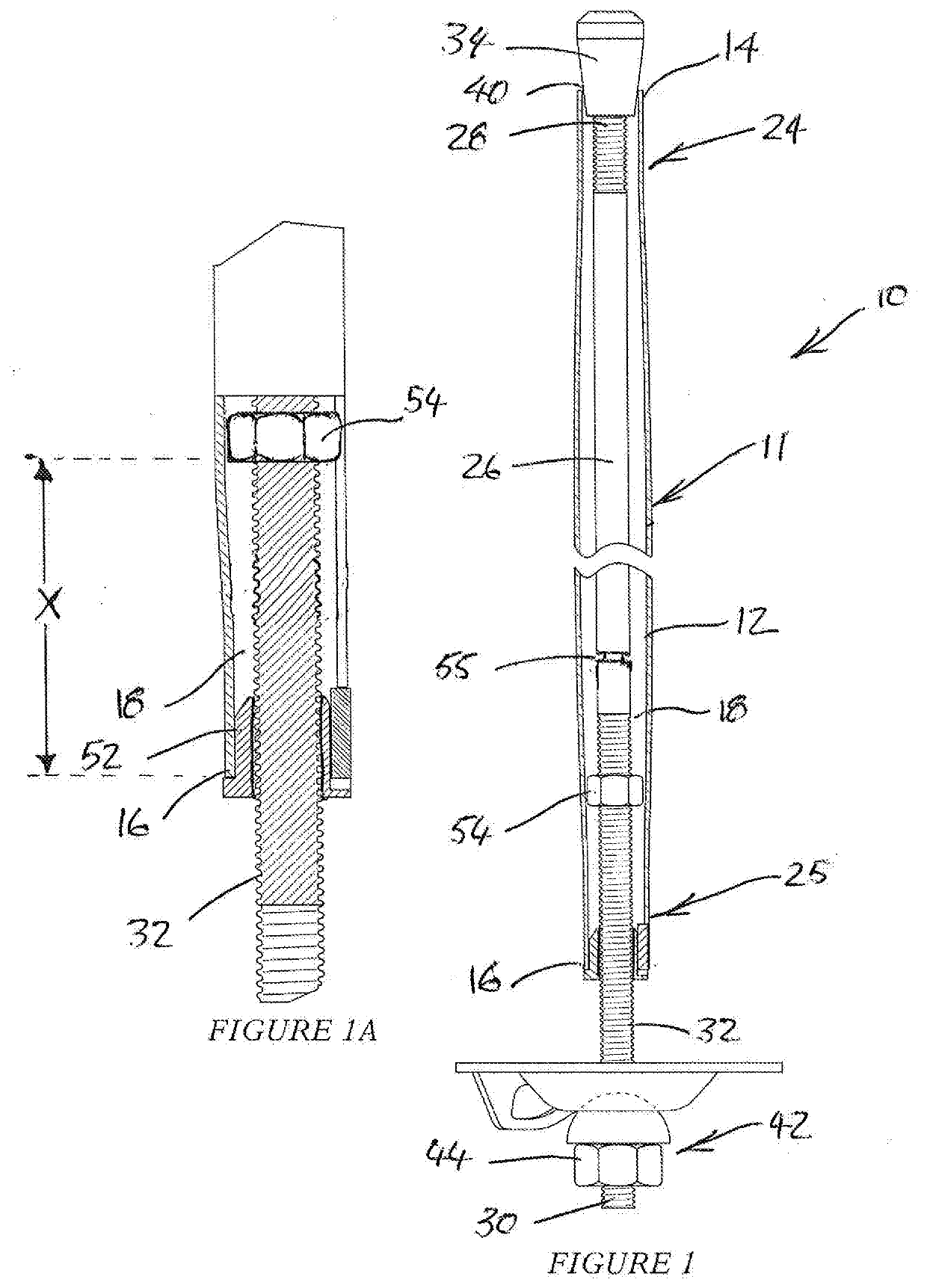
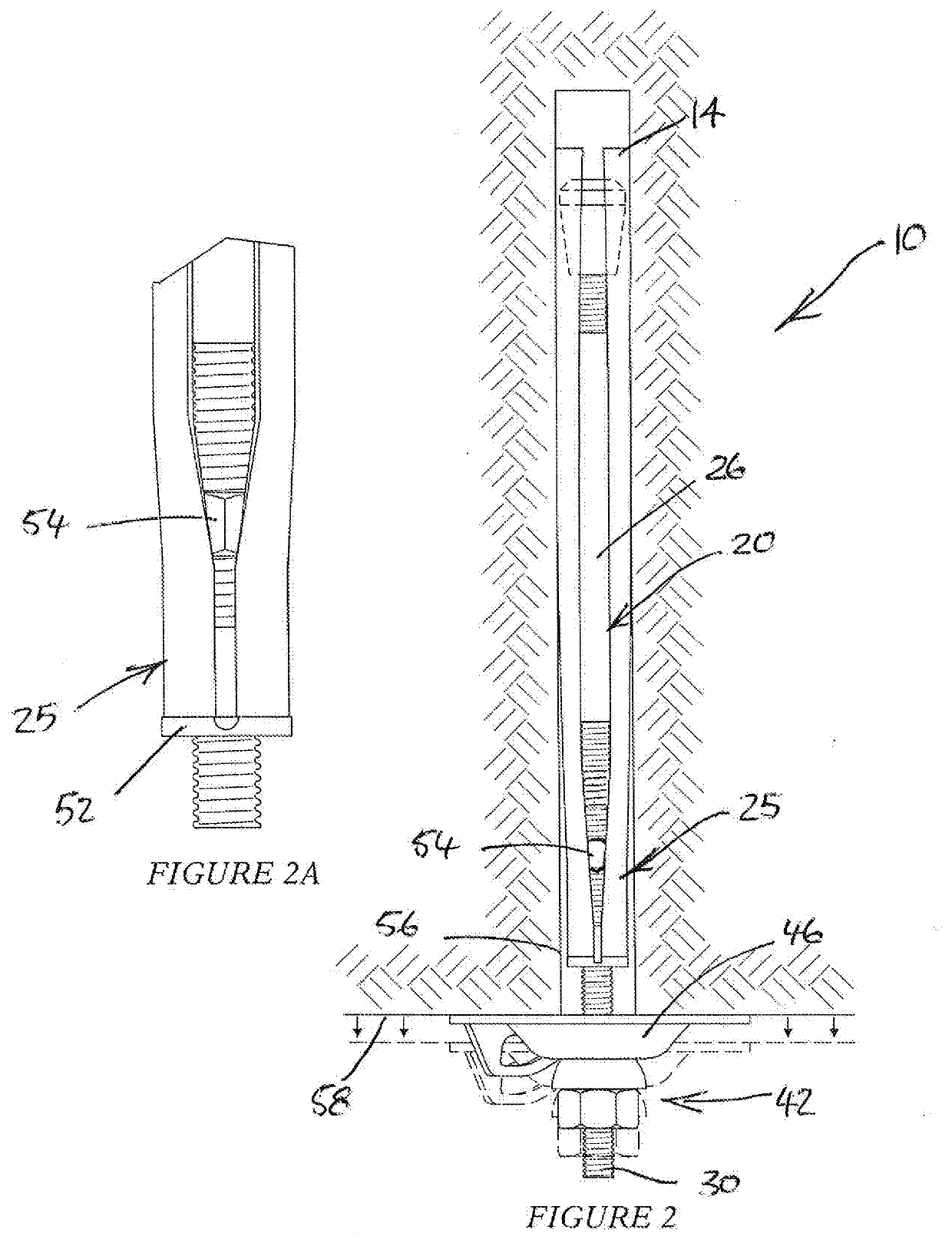
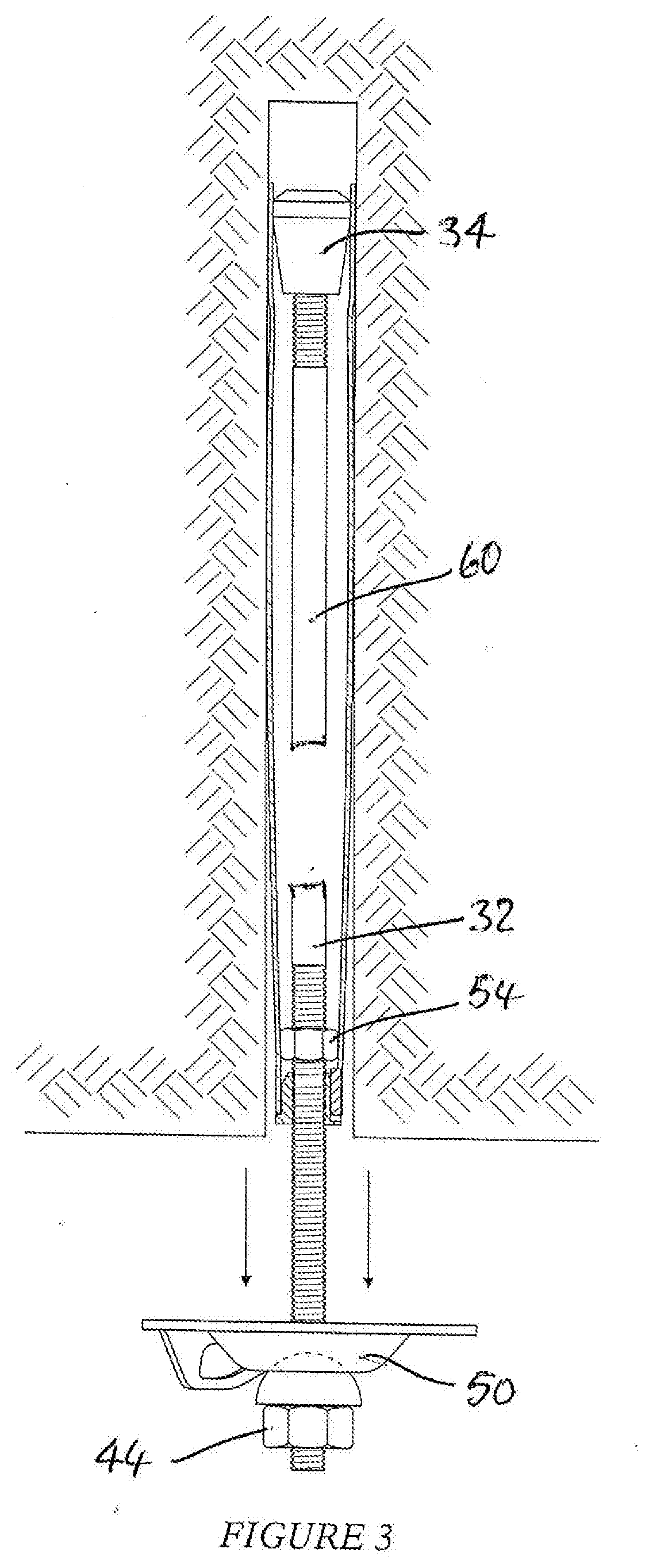
[0022]A rock anchor assembly 10 according to the invention is depicted in FIGS. 1 to 3 of the accompanying drawings.

[0023]The rock anchor assembly 10 has a resiliently radially deformable sleeve 11 having a generally tubular body 12 that longitudinally extends between a leading end 14 and a trailing end 16. Within the sleeve body, a cavity 18 is defined. The body 12 has a slit 20 extending along the body from a point of origin towards the trailing end 16 and ending at the leading end 14. The slit provides for radial compression of the tubular sleeve body as the body is inserted into a rock hole as will be described in greater detail below.

[0024]The sleeve body 12 has a slightly tapered leading portion 24 that tapers toward the leading end 14 to enable the sleeve 11 to be driven into a rock hole having a smaller diameter than the body. At an opposed end, the sleeve body has a tapered trailing portion 25, the function of which will be described below. Between the leading and trailing ...

second embodiment

[0042]the rock anchor assembly 10A is illustrated in FIG. 4. In describing this embodiment, like features bear like designations. Only the differences over the earlier embodiment are described.

[0043]The assembly 10A includes an arrestor element 62, such as a collar of bush, which is welded to the inside surface of the proximal portion 25 of the sleeve 11. Although a tapered proximal portion is illustrated in this figure, this tapering is not essential and, instead, the sleeve diameter reduction is achieved with the arrestor element.

[0044]It is against this element that the failure arrestor comes into contact. In this embodiment, the failure arrestor 54A is a paddle shaped adaptation of the rod 26.

[0045]In the embodiments described above, the sleeve 11 and the elongate element 26 are made of structural grade steel. This is non-limiting to the invention as it is envisaged that at least the sleeve 11 and the elongate element 26 can also be made of a fibre reinforced plastic (FRP) such ...


PUM


Abstract

A rock anchor assembly includes: a resiliently radially deformable tubular member longitudinally extending between leading and trailing ends and which has an arrestor formation integral with, or engaged to, a trailing end part of the member; an elongate element longitudinally extending through the member between first and second ends and which attaches to the tubular member at spaced distal and proximal load points and which has a failure arrestor fixed at a point within the member; and a faceplate on the tubular member or the elongate member. When the assembly is inserted in a rock hole, with the faceplate bearing against the rock face, and load is applied along the elongate element that will cause the element to sever above the point at which the arrestor is fixed, the failure arrestor engages the arrestor formation, arresting the ejectment of a proximal portion of the elongate element from the hole.

Description

BACKGROUND OF THE INVENTION[0001]The invention relates to a rock anchor assembly.[0002]In a dynamic load support environment, a rock anchor prevents catastrophic failure of the rock wall, which the anchor supports, by absorbing the energy of the rock movement by stretching. A problem arises in an ungrouted application when the steel material of the rock anchor deforms to its maximum tensile capacity, whereafter the anchor is prone to snap. As the anchor is in tension, the moment the anchor breaks, its proximal severed section has a tendency to eject from the rock hole at great force. This creates a projectile which poses a great danger to mine workers in the vicinity.[0003]The invention aims to overcome the problem by providing a mechanism to arrest the detached portion of steel as it attempts to eject from the support hole.[0004]The present invention at least partially addresses the aforementioned problem.SUMMARY OF INVENTION[0005]The invention provides a rock anchor assembly which...

Claims


Application Information

Patent Timeline
Patent Type & Authority Applications(United States)
IPC IPC(8): E21D21/00
CPCE21D21/004E21D21/0033E21D21/0026E21D21/008
Inventor PASTORINO, PAOLO ETTOREABREU, RUALKNOX, GREG
Owner EPIROC DRILLING TOOLS AB
Why Eureka
Try Eureka