Internal thread member, external thread member, and cutter for internal thread

a technology for internal threads and cutters, which is applied in the direction of threaded fasteners, screw heads, manufacturing tools, etc., can solve the problems of shortened cutter life, easy chipping or damage, and the tip (or crest) of the cutting edge of the cutter tends to wear out quickly, so as to reduce the diameter of the internal thread at the thread root position, the effect of stable finishing accuracy and large radius

Active Publication Date: 2006-06-29
BIG ALPHA CO LTD
View PDF15 Cites 11 Cited by
  • Summary
  • Abstract
  • Description
  • Claims
  • Application Information

AI Technical Summary

Benefits of technology

[0031] Since the rounded root of the internal thread member of this invention can have a large radius, it is possible to obtain stable finishing accuracy. Moreover, since it is possible for the rounded root of the internal thread to have a large radius, the diameter of the internal thread at the thread root position can be reduced. Accordingly, it is also possible to reduce the outside diameter of the internal thread. Furthermore, when its height of thread engagement on the external thread side with reference to the pitch diameter is larger than the height of thread engagement on the internal thread side, the contact region of the internal thread with the external thread is positioned closer to the inside diameter side and away from the outside diameter side. Consequently, the area of the contact region becomes smaller and the distance from the center of the threads to a force generating position is shortened, thereby making it possible to reduce the force necessary to turn the threads.
[0032] Moreover, concerning the external thread member of this invention, the contact region of the external thread with the internal thread is positioned closer to the inside diameter side and away from the outside diameter side. Consequently, the area of the contact region of the external thread with the internal thread becomes smaller and the distance from the center of the threads to a force generating position is shortened, thereby making it possible to reduce the force necessary to turn the threads. Since it is also possible to form the top of the thread crest in a comparatively flat shape, the safety is assured even if the top of the thread crest is exposed.
[0033] Furthermore, since the cutter for machining the internal thread of this invention comprises a comparatively large arc (in the shape complementary to that of the thread root of the internal thread) at the top of its thread crest, it is possible to enhance the fracture resistance and the wear and abrasion resistance. Accordingly, it is possible to improve the finishing accuracy and to assure the long life.

Problems solved by technology

When machining an internal thread that has a rounded root of a small radius, the tip (or crest) of the cutting edge of the cutter tends to wear out quickly and to easily become chipped or to suffer damage.
Accordingly, there is a possibility that it may become difficult to secure stable finishing accuracy and the life of the cutter may be shortened.
Moreover, as described above, if the rounded root of the internal thread is designed to have a large radius, its thread overlap becomes small, thereby making it difficult to secure sufficient breaking strength and pullout strength.

Method used


Image

  • Internal thread member, external thread member, and cutter for internal thread
  • Internal thread member, external thread member, and cutter for internal thread
  • Internal thread member, external thread member, and cutter for internal thread

Examples


embodiment 1

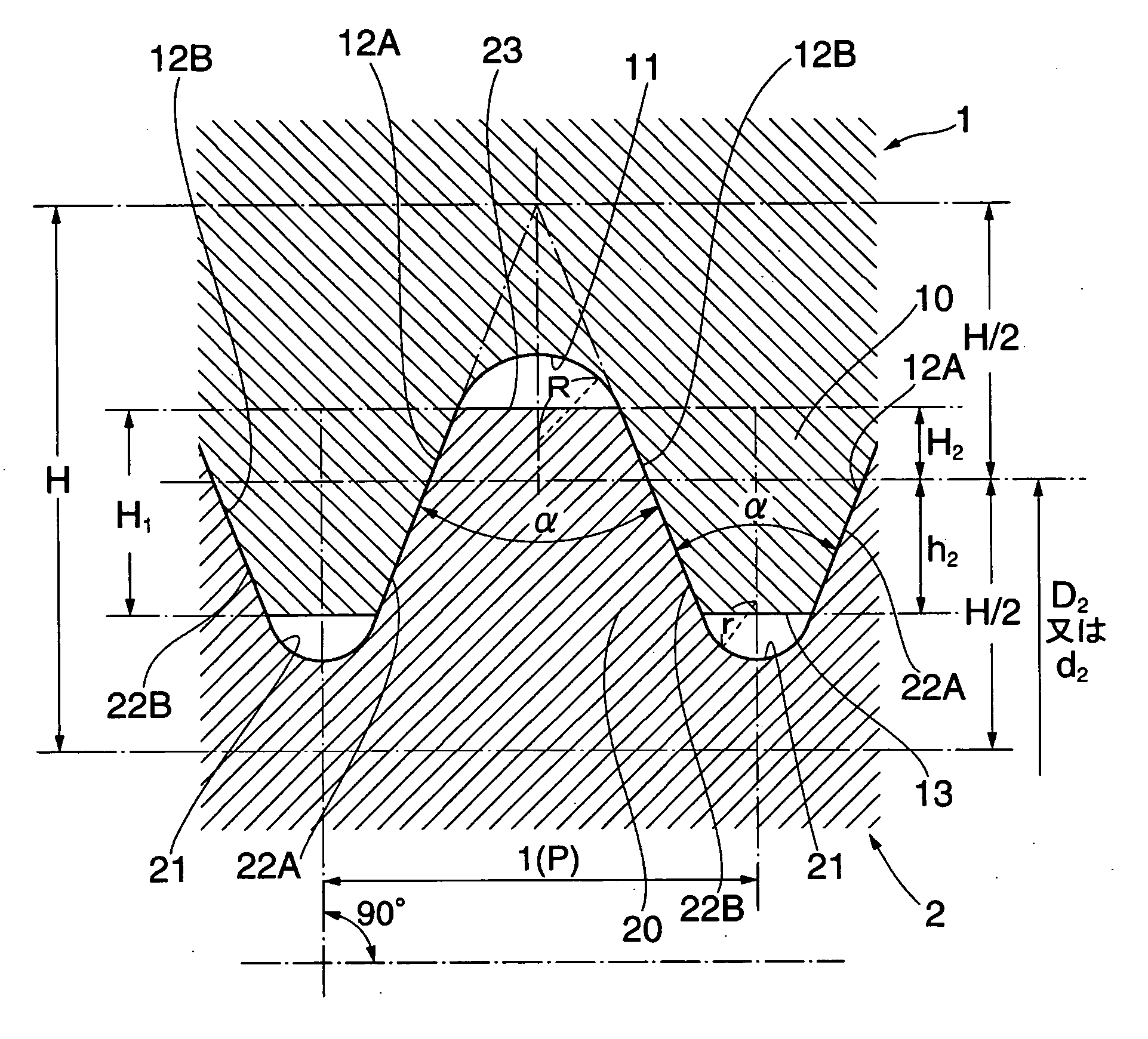
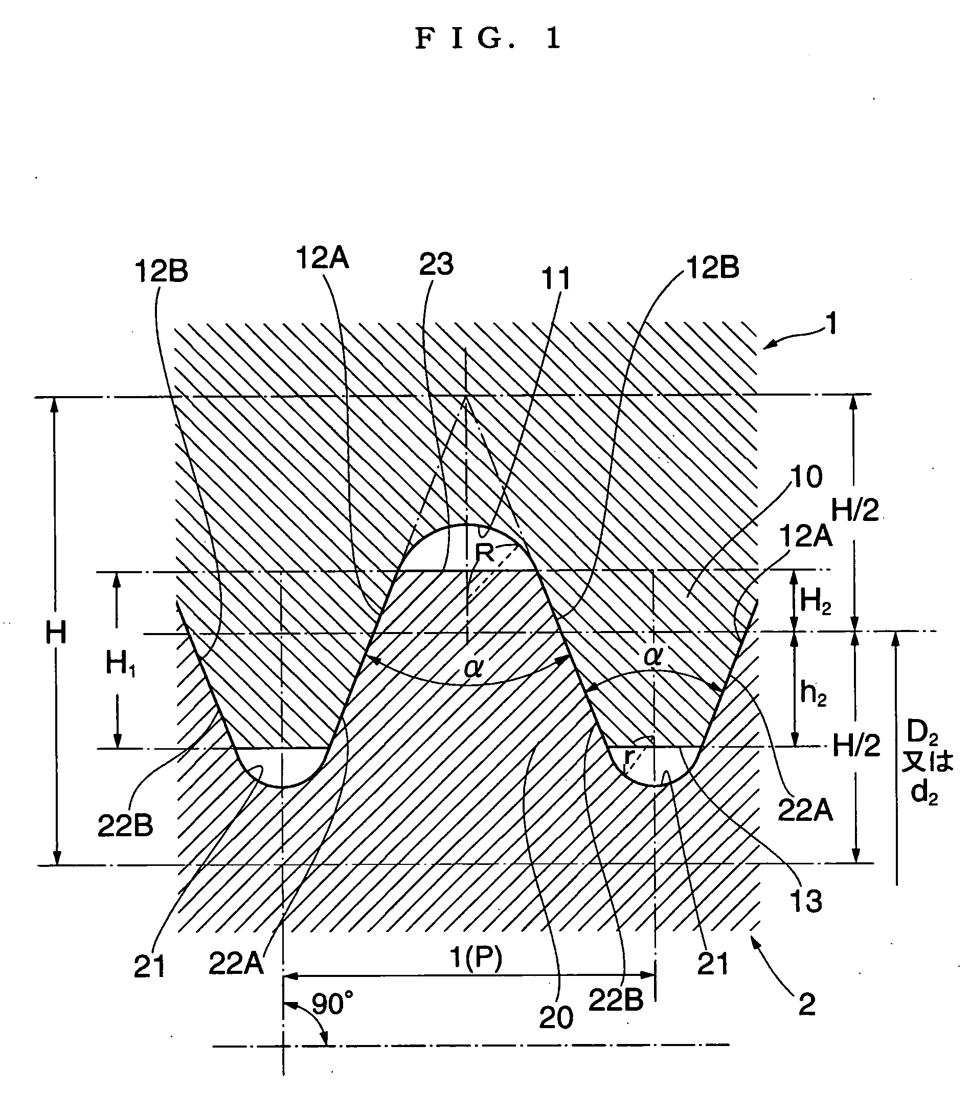
[0042]FIG. 1 is a sectional view that illustrates a part of an internal thread member and an external thread member according to Embodiment 1 of this invention in the state where the internal thread member engages with the external thread member.

[0043] As shown in FIG. 1, an internal thread member 1 of Embodiment 1 has an internal thread 10 formed around its inside surface. Concerning this internal thread 10, the pitch (P) is 1 mm, the angle (α) of a thread is 45 degrees, and extension lines of both its flanks 12A and 12B intersect with each other. A thread root 11 of the internal thread 10 consists of an arc (radius (R)=0.2 mm) that is smoothly connected to both the flanks 12A and 12B. A thread crest 13 of the internal thread 10 is shaped as a flat plane positioned close to the ends of an arc (radius (r)=0.125 mm) that forms a thread root 21 of an external thread 20 described below. This internal thread 10 is structured in such a manner that its height of thread engagement (h2) on...

embodiment 2

[0059] A cutter for machining the internal thread of the internal thread member of this invention is described below with reference to the relevant drawings. Concerning Embodiment 2, an explanation is given about the cutter (or screw tap) for machining the internal thread 10 of the internal thread member 1 described in Embodiment 1.

[0060]FIG. 3 is a side view of the screw tap. FIG. 4 is an enlarged fragmentary sectional view of the screw tap as taken along line IV-IV shown in FIG. 3.

[0061] As shown in FIGS. 3 and 4, a screw tap 3 of Embodiment 2 comprises: a shank 31; and a thread unit 32 formed at the top end of the shank 31.

[0062] The number of flutes formed in the thread unit 32 is four. The thread unit 32 comprises: a complete thread crest part 33 formed on the shank 31 side; and an chamfer part 34 which is connected to the complete thread crest part 33 and whose outside diameter gradually becomes smaller toward its top-end side.

[0063] The complete thread crest part 33 is st...


PUM


Abstract

The present invention provides an internal thread member and an external thread member that can achieve stable finishing accuracy, can assure a desirable thread overlap, and have sufficient breaking strength and pullout strength. This invention also provides a cutter which can machine internal threads with stable finishing accuracy and can assure improved durability.

Description

CROSS-REFERENCE TO RELATED APPLICATION [0001] This application claims the priority under 35 U.S.C. §119 of Japanese Patent Application No. 2003-362756 filed Oct. 23, 2003. BACKGROUND [0002] The present invention relates to an internal thread member, an external thread member, and a cutter for machining an internal thread. [0003] As basic screw shapes, the JIS standards have included descriptions of, for example, miniature thread screws, pipe screw threads, metric screw threads, unified screw threads, and cycle threads. Specifically, please refer to JIS B 0201 “Miniature Screw Threads,” JIS B 0202 “Parallel Pipe Threads,” JIS B 0205 “Metric Coarse Screw Threads,” JIS B 0206 “Unified Coarse Screw Threads,” JIS B 0216 “Metric Trapezoidal Screw Threads,” and JIS B 0225 “Cycle Threads.”[0004] Since threads are cut in an external thread along its outside surface, it is easy to machine the external thread. According to the JIS standards, for performance reasons, a rounded root of the exter...

Claims


Application Information

Patent Timeline
Patent Type & Authority Applications(United States)
IPC IPC(8): F16B39/30B23G5/06F16B33/02
CPCB23G5/06F16B33/02E05B45/06E05B65/025
Inventor KOMINE, TSUYOSHI
Owner BIG ALPHA CO LTD
Why Eureka
Try Eureka