Dynamic sealing arrangement for movable shaft

a technology of dynamic sealing and moving shafts, applied in the direction of valve arrangements, spindle sealings, engine seals, etc., can solve the problems of complex plumbing arrangements, inability to structurally implement, and inability to meet the requirements of movable shafts, etc., to prevent dust ingress.

Inactive Publication Date: 2006-10-10
WOODWARD GOVERNOR CO
View PDF69 Cites 45 Cited by
  • Summary
  • Abstract
  • Description
  • Claims
  • Application Information

AI Technical Summary

Benefits of technology

[0007]One aspect of the preferred embodiment is that the third seal is arranged as an external seal proximate the external environment to prevent ingress of dust, grit and other contaminants, thereby ensuring that the seals which are subject to axial barrier sealant loads are free of contaminants from the external contaminant that could cause premature failure.
[0008]In accordance with another aspect of the present invention, a unitary seal block member is provided that supports the dynamic sealing arrangement for the shaft and defines a piston chamber and a drilled passageway connecting the piston chamber and barrier sealant pressurization chamber between two seals. Thus, a substantial amount of plumbing is self contained in a single body minimizing the need for additional components or complexity.

Problems solved by technology

The problem with the concepts disclosed in the foregoing patents is that the concepts appear to be complex and costly to implement.
More specifically, these proposals have complex plumbing arrangements, are not practical to structurally implement, and / or require numerous complex components for establishing a preload barrier.
Further, the indicating mechanism disclosed in at least some of these patents may have accuracy problems, may not readily indicate the exact source of the problem and / or may be difficult or impractical to implement in the field or across different applications.

Method used


Image

  • Dynamic sealing arrangement for movable shaft
  • Dynamic sealing arrangement for movable shaft
  • Dynamic sealing arrangement for movable shaft

Examples


Embodiment Construction

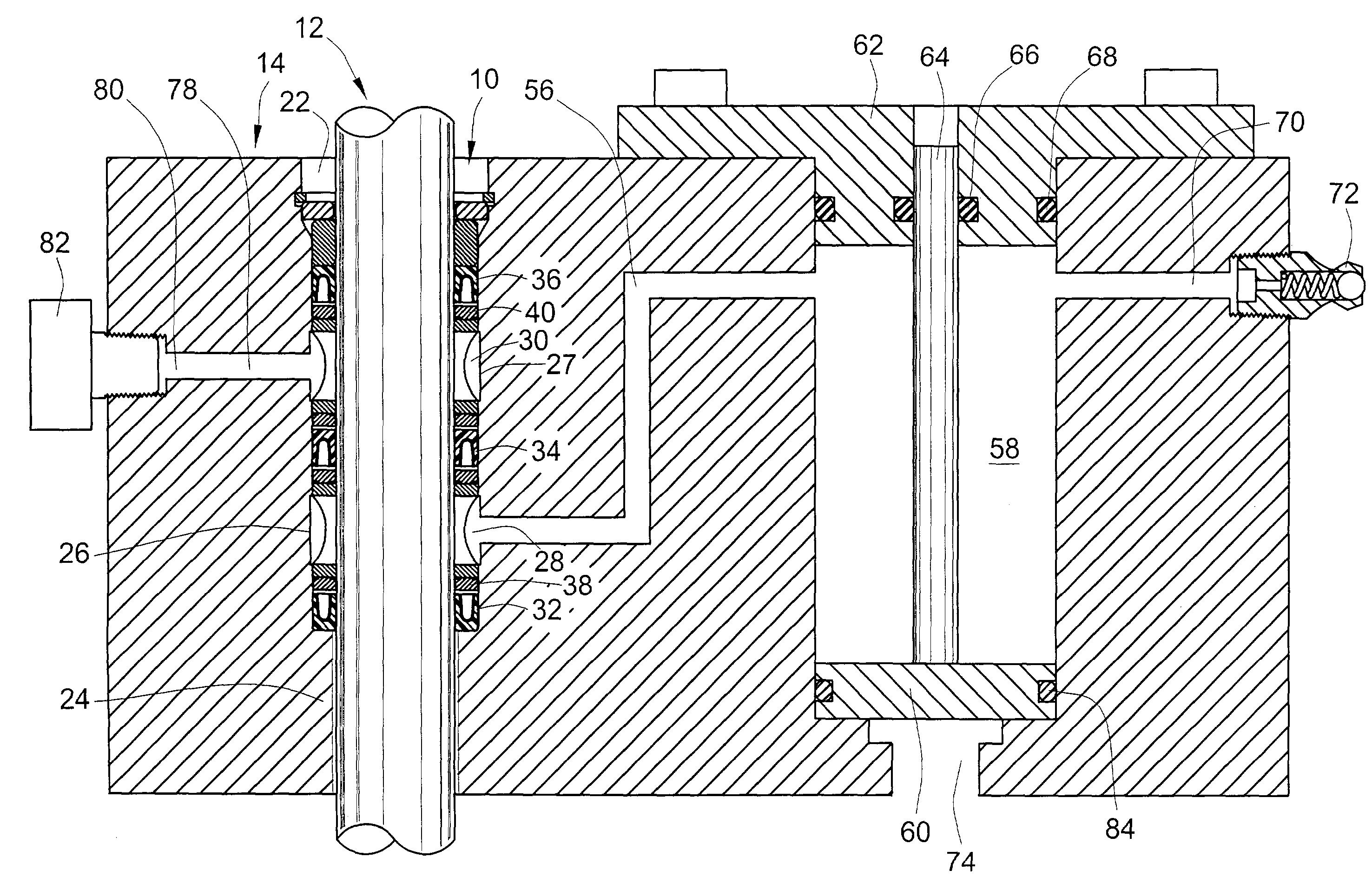
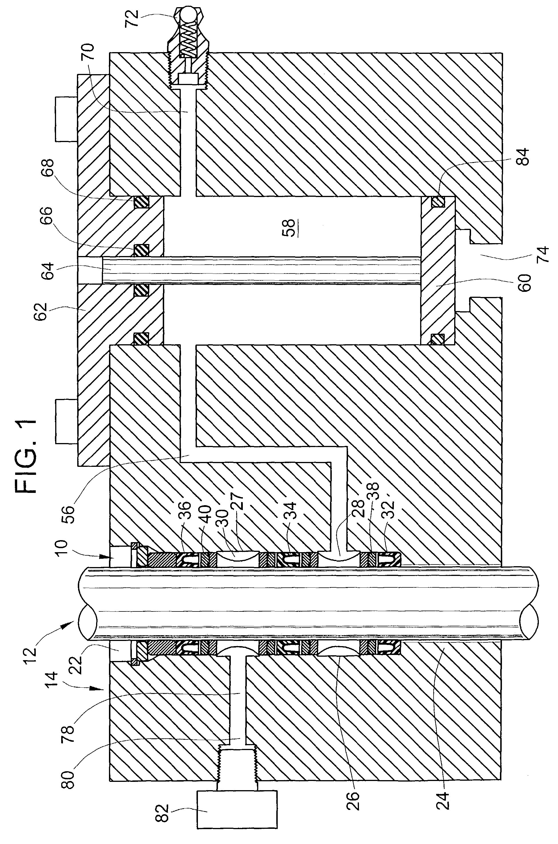
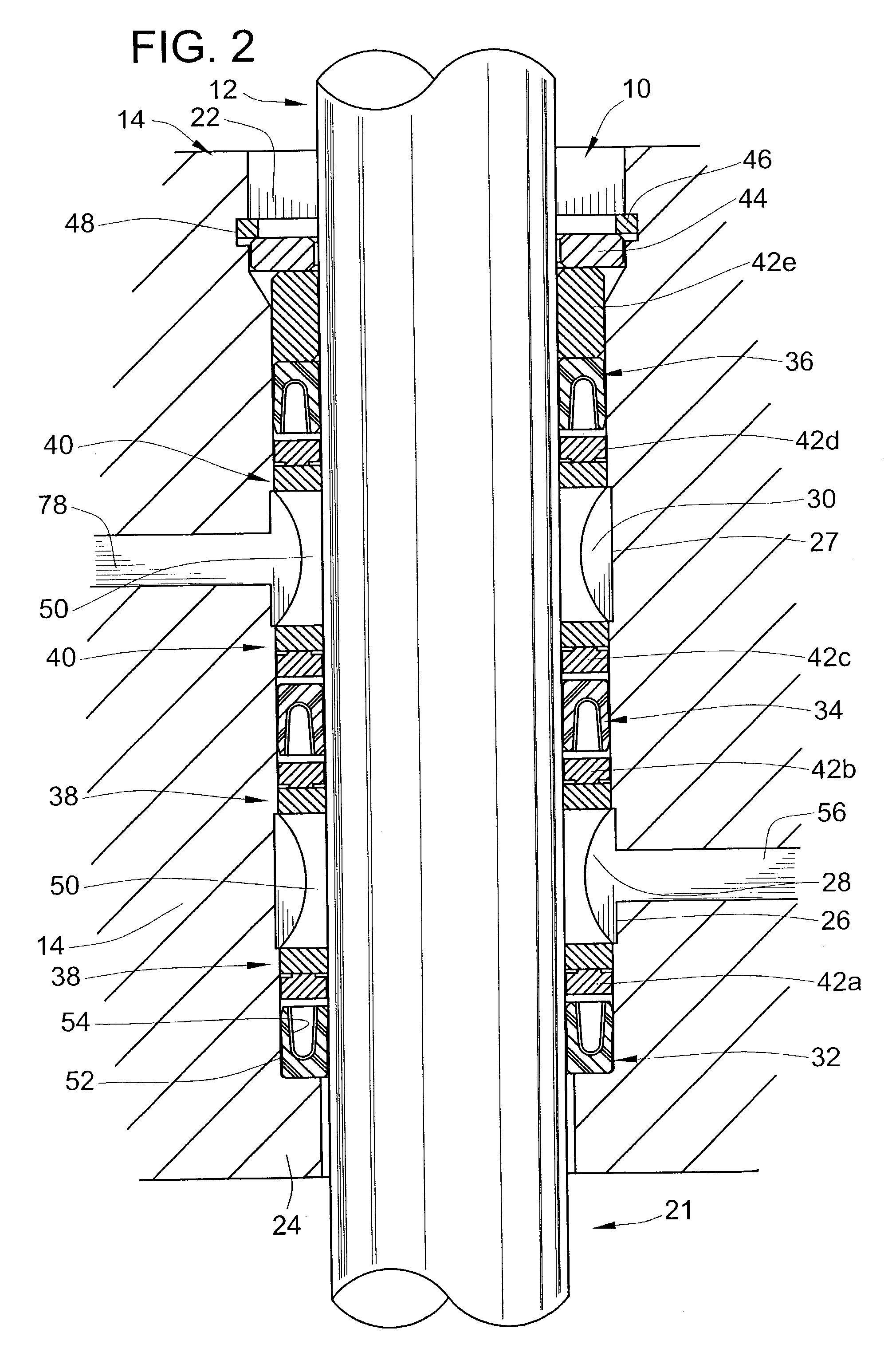
[0015]Referring to FIG. 3, a preferred embodiment of the present invention has been illustrated as a seal assembly 10 for preventing leakage of process fluid and for preventing ingress of dirt, contaminants and other foreign material along a movable shaft 12. The invention is preferably incorporated into a separate seal block member 14, or other appropriate type of housing. In the preferred embodiment, the seal block member 14 is sandwiched between a spring housing 16 and a valve body 17. The movable shaft 12 may be linearly and or rotatably translatable. As shown herein, the movable shaft 12 is integrally connected to a valve member 20 that slides linearly in the valve body 17 to regulate process fluid flow along a valve passageway 21.

[0016]The novel sealing arrangement as shown herein may be employed in an electrically actuated well head valve as disclosed in Greeb et al., U.S. patent application Ser. No. 10 / 340,017, filed on Jan. 10, 2003, assigned to Woodward Governor Company, t...


PUM


Abstract

A dynamic sealing arrangement for preventing leakage of a fluid along a shaft includes multiple seals and pressurized barrier sealant. According to one aspect, at least three seals are arranged along the shaft with pressurized barrier sealant between the first and second seals and a collection area is provided between the second and third seals to collect any leakage that might occur. Collected leakage, if any, is ported to an output port. According to another aspect, a unitary seal block member is provided that supports the dynamic sealing arrangement for the shaft and defines a piston chamber and a drilled passageway connecting the piston chamber and barrier sealant pressurization chamber between two seals. A substantial amount of plumbing is self contained in a single body minimizing the need for additional components or complexity.

Description

FIELD OF THE INVENTION[0001]This invention pertains to seal assemblies and more particularly to pressurized dynamic seal arrangements.BACKGROUND OF THE INVENTION[0002]The proposed use of a pressurized barrier sealant fluid between two seals for fluid control apparatus such as pumps, valves and the like is generally known. For example, pressurized dynamic shaft sealing arrangements are disclosed in U.S. Pat. No. 5,746,435 to Arbuckle, U.S. Pat. No. 6,161,835 to Arbuckle, U.S. Pat. No. 5,772,216 to Bredemeyer and U.S. Pat. No. 5,607,165 to Bredemeyer. Such pressurized dynamic sealing arrangements may be used in the process gas industry for valves and the like to better ensure that process gas (e.g. natural gas, gaseous fuel, etc.) does not leak or cause a hazardous external environment.[0003]These patents disclose that use of pressurized barrier sealant provides opposing axial fluid forces on two spaced apart seals. In these arrangements, the barrier sealant fluid pressure is typicall...

Claims


Application Information

Patent Timeline
Patent Type & Authority Patents(United States)
IPC IPC(8): F16J15/18F16J15/32F16J15/00F16J15/40F16K41/04
CPCF16J15/004F16J15/406F16K41/04
Inventor BURDICK, WADE A.BOWMAN, GARY M.
Owner WOODWARD GOVERNOR CO
Why Eureka
Try Eureka