Composite spar drape forming machine

a composite fiber and forming machine technology, applied in the field of composite fiber laminate parts forming machine, can solve the problems of inability to form composite charges with aggregate laminate ply thicknesses greater than 0.25 inches without buckling or out-of-plane fiber distortion, machine forming system configuration for single-part manufacturing and have not been reconfigured, and achieve efficient and accurate positioning of composite charges over mandrels prior to forming. , the effect of space effectiv

Inactive Publication Date: 2006-10-10
THE BOEING CO
View PDF10 Cites 62 Cited by
  • Summary
  • Abstract
  • Description
  • Claims
  • Application Information

AI Technical Summary

Benefits of technology

[0008]The present invention is re-configurable to mold different parts, provides for the efficient and accurate positioning of com

Problems solved by technology

However, these methods and systems have not been able to form composite charges with aggregate laminate ply thicknesses greater than 0.25 inches without buckling or out-of-plane fiber distortion.
Further, machine forming systems have been configured for single part manufacturing and have not been reconfigurable.
Alignment o

Method used


Image

  • Composite spar drape forming machine
  • Composite spar drape forming machine
  • Composite spar drape forming machine

Examples


Embodiment Construction

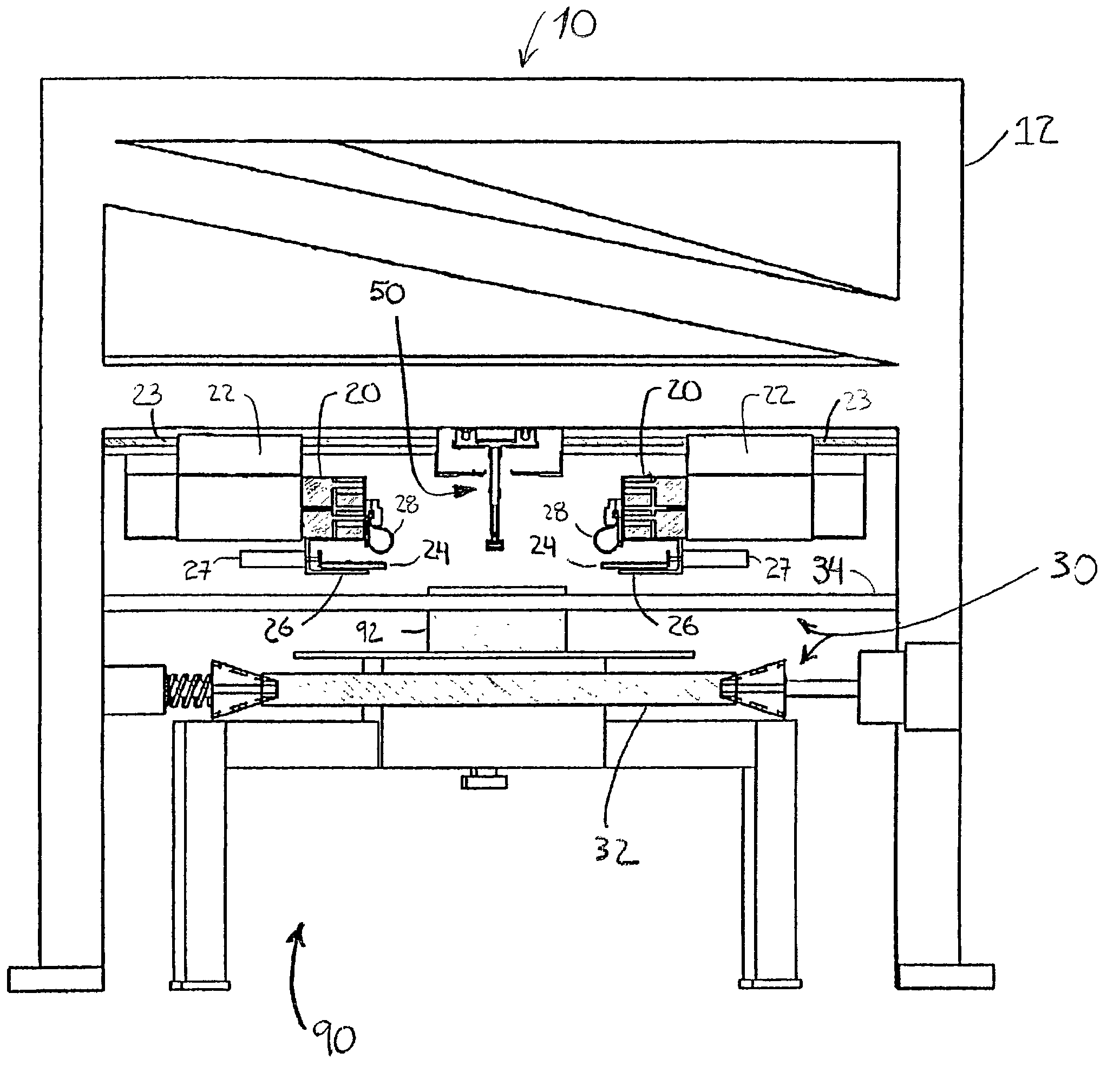
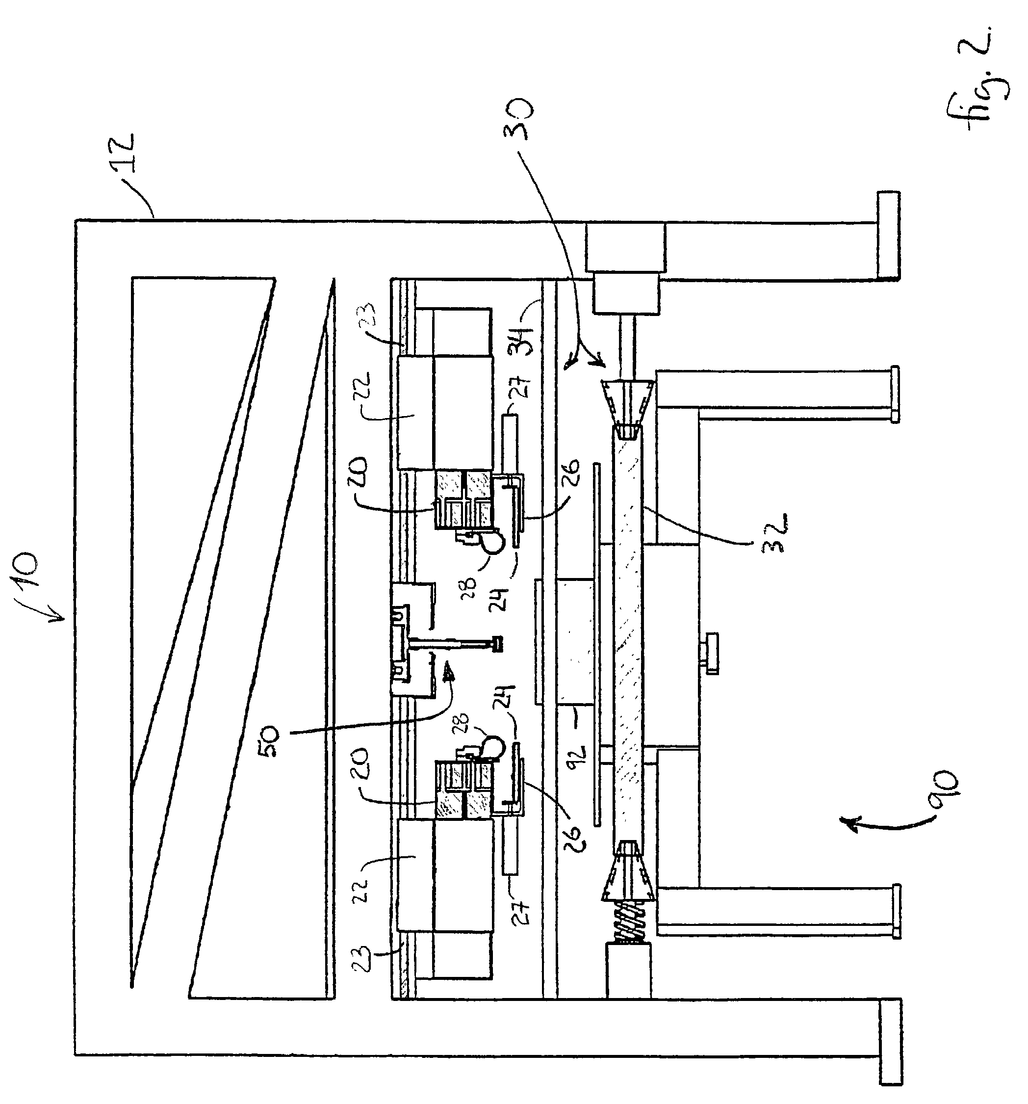
[0022]A machine and a method for forming composite materials are provided. By way of overview, the machine includes a frame and at least one forming beam attached to the frame, the at least one beam being arranged to align with a mandrel. The forming beam is pivotally segmented into at least two segments to conform to the shape of the mandrel or alternately is bendable to conform to the shape of the mandrel. The mandrel is receivable within the frame in alignment with the forming beam.

[0023]An apparatus is also provided to position a composite charge over the mandrel and to position the mandrel within the frame. A further apparatus is provided to transport the mandrel and to urge the mandrel toward the forming beam.

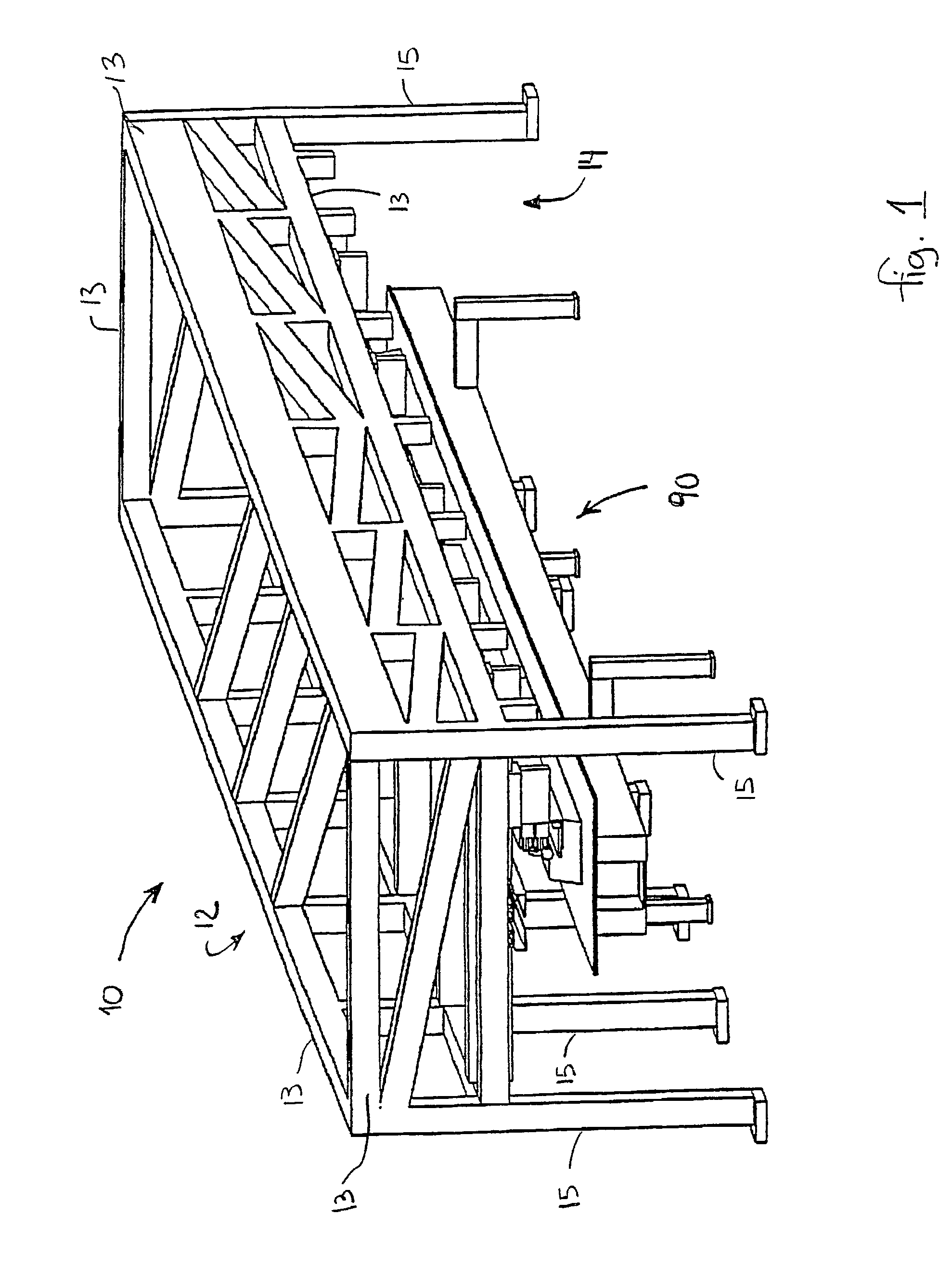
[0024]FIG. 1 illustrates an example drape forming machine 10 of the present invention. In this embodiment, the machine 10 has a frame 12 with an open side 14. A mandrel tool 90 removably fits within the open side 14 of the frame 12. Composite parts such as beams and aircr...


PUM

PropertyMeasurementUnit
Lengthaaaaaaaaaa

Abstract

A machine and a method for forming composite materials are provided. The machine includes a frame and at least one forming beam attached to the frame, the at least one beam being arranged to align with a mandrel. The forming beam is pivotally segmented into at least two segments to conform to the shape of the mandrel, or alternately is bendable to conform to the shape of the mandrel. The mandrel is receivable within the frame in alignment with the forming beam. An apparatus is also provided to position a composite charge over the mandrel, and to position the mandrel within the frame. A further apparatus is provided to transport the mandrel, and to urge the mandrel toward the forming beam, forming a composite charge.

Description

RELATED APPLICATIONS[0001]This application is related to concurrently filed patent application Ser. No. 10 / 233,270 entitled, “Forming Method for Composites,” the contents of which are hereby incorporated by this reference.FIELD OF THE INVENTION[0002]This invention relates generally to the forming of composite fiber laminate parts, and, more specifically, to machine forming of composite materials.BACKGROUND OF THE INVENTION[0003]Composite materials, including carbon fiber epoxy impregnated laminates, are commonly used in applications requiring high strength and light weight. Forming composite material ply packages or charges has generally been done by hand, especially when the laminate plys of the composite materials exceed 0.25 inch in thickness. Forming large compound shaped composite material charges over a forming tool or mandrel can often take 2 to 3 days. The laid-up parts are then cured.[0004]Machines have been utilized to form composite material charges over forming mandrel. ...

Claims


Application Information

Patent Timeline
IPC IPC(8): B29C70/44B29C33/30B29C70/34B29C70/54
CPCB29C70/342B29C70/541B29C33/307B29C51/087
Inventor WILLDEN, KURTIS S.HENDERSON, RAYMOND N.PFITZNER, GARY E.PAREKH, SURENDRA R.HARRIS, CHRISTOPHER G.
Owner THE BOEING CO
Why Eureka
Try Eureka