Socket connecting structure

a socket and socket technology, applied in the direction of coupling device connection, contact member penetrating/cutting insulation/cable strand, application, etc., can solve the problems of socket being detached from the socket rack, the connection between the socket and the socket rack may be weakened, etc., to achieve the effect of improving the socket connection structure and prolonging the use li

Inactive Publication Date: 2006-10-10
DANAHER TOOL TAIWAN BRANCH
View PDF5 Cites 10 Cited by
  • Summary
  • Abstract
  • Description
  • Claims
  • Application Information

AI Technical Summary

Benefits of technology

[0006]The main objective of the present invention is to provide an improved socket connecting structure that has a lengthened use life.

Problems solved by technology

Consequently, the connection between the socket and the socket rack may be weakened and extremely, the socket may be detached from the socket rack when the socket rack is worn out.

Method used


Image

  • Socket connecting structure
  • Socket connecting structure
  • Socket connecting structure

Examples


second embodiment

[0018]With reference to FIG. 5 that shows the socket connecting structure in accordance with the present invention, the connecting portion (21) is altered to be a suspension card (25) and the stub (22) is connected to a lower portion of the suspension card (25). Consequently, the socket (30) can be displayed in a market when being connected to the stub (22).

third embodiment

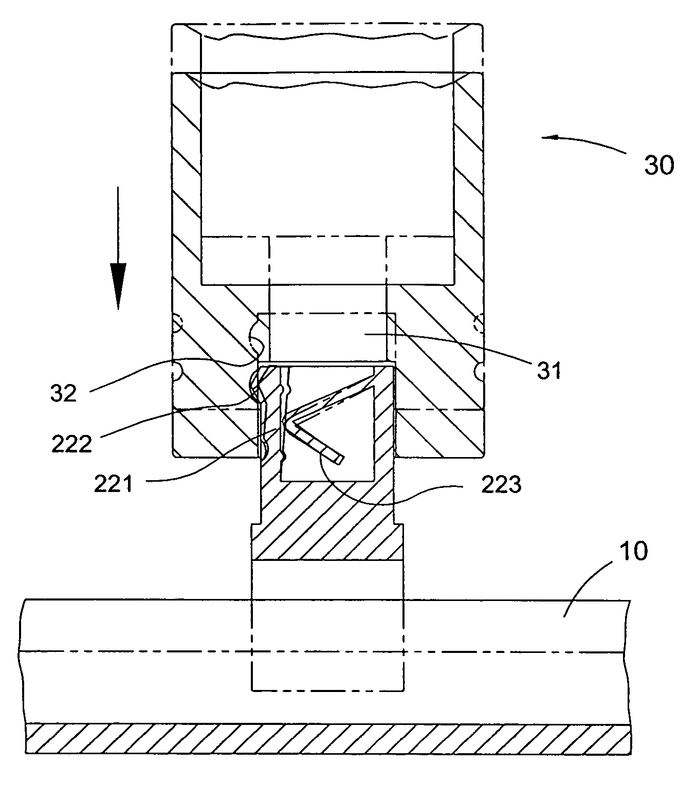
[0019]With reference to FIG. 6 that shows the socket connecting structure in accordance with the present invention, a metal stick (28) has a first end securely inserted into a bottom of the stub (22) and a curved second end. The curved second end of the metal stick (28) is received in an indentation (32) that is defined in the inner periphery of the cubic hole (31) of the socket to hold the socket (30) in place when the socket is moved to the specific location.


PUM


Abstract

A socket connecting structure includes a connecting portion disposed on a suspension element and a stub extending from the connecting portion, wherein the stub is connected to a socket. The stub has a resilient stick formed on one side thereof and a spring formed within the stub. The spring has one end connected to an inner periphery of the stub and abuts a back of the resilient stick to provide a thrust to the resilient stick for connecting the socket when the resilient stick is worn out.

Description

BACKGROUND OF THE INVENTION[0001]1. Field of the Invention[0002]The present invention relates to a connecting structure, and more particularly to a socket connecting structure.[0003]2. Description of Related Art[0004]As well known, the socket is attached to the socket rack due to a friction force between the socket and the socket rack. Consequently, the connection between the socket and the socket rack may be weakened and extremely, the socket may be detached from the socket rack when the socket rack is worn out.[0005]The present invention has arisen to mitigate and / or obviate the disadvantages of the conventional socket connecting structure.SUMMARY OF THE INVENTION[0006]The main objective of the present invention is to provide an improved socket connecting structure that has a lengthened use life.[0007]To achieve the objective, the socket connecting structure in accordance with the present invention comprises a connecting portion disposed on a suspension element and a stub extendin...

Claims


Application Information

Patent Timeline
Patent Type & Authority Patents(United States)
IPC IPC(8): H01R11/20
CPCH01R13/506H01R13/508H01R25/142
Inventor MU, HSIEN-CHUNG TUANTSAI, SAMMY
Owner DANAHER TOOL TAIWAN BRANCH
Why Eureka
Try Eureka