
Steel structure corridor structure and hoisting construction method

A technology for steel structures and corridors, which is applied in building construction, construction, and building materials processing, etc., can solve the problems of high installation requirements, poor positioning effect, inconvenient installation of steel structure corridors, etc. Corridor, increase the effect of connecting structure

Active Publication Date: 2020-05-29
广东省构建工程建设有限公司
View PDF5 Cites 8 Cited by
  • Summary
  • Abstract
  • Description
  • Claims
  • Application Information

AI Technical Summary

Problems solved by technology

The self-weight of the steel structure corridor assembled on the ground is relatively large, which is not conducive to hoisting operations, and the installation requirements are relatively high; after lifting in stages to install the spliced ​​steel structure corridor, it is necessary to build a construction platform on the ground, after hoisting the steel structure components , welding steel structural members on the construction platform
[0005] The above-mentioned existing technical solutions have the following defects: the components of the existing steel structure corridor are usually connected by welding. When connecting the components, it is necessary to position and place the components between the components. The existing steel structure The components are generally welded by manual positioning, and the positioning effect is poor, which easily affects the structural stability of the steel structure corridor. The hoisting construction method of the steel structure corridor, whether it is to use ground connection and assembly, or choose to build a construction platform on the ground, and then Welding in the air has the above problems, and it is not convenient to install steel structure corridors

Method used


Image

  • Steel structure corridor structure and hoisting construction method
  • Steel structure corridor structure and hoisting construction method
  • Steel structure corridor structure and hoisting construction method

Examples


Embodiment Construction

[0046] The present invention will be described in further detail below in conjunction with the accompanying drawings.

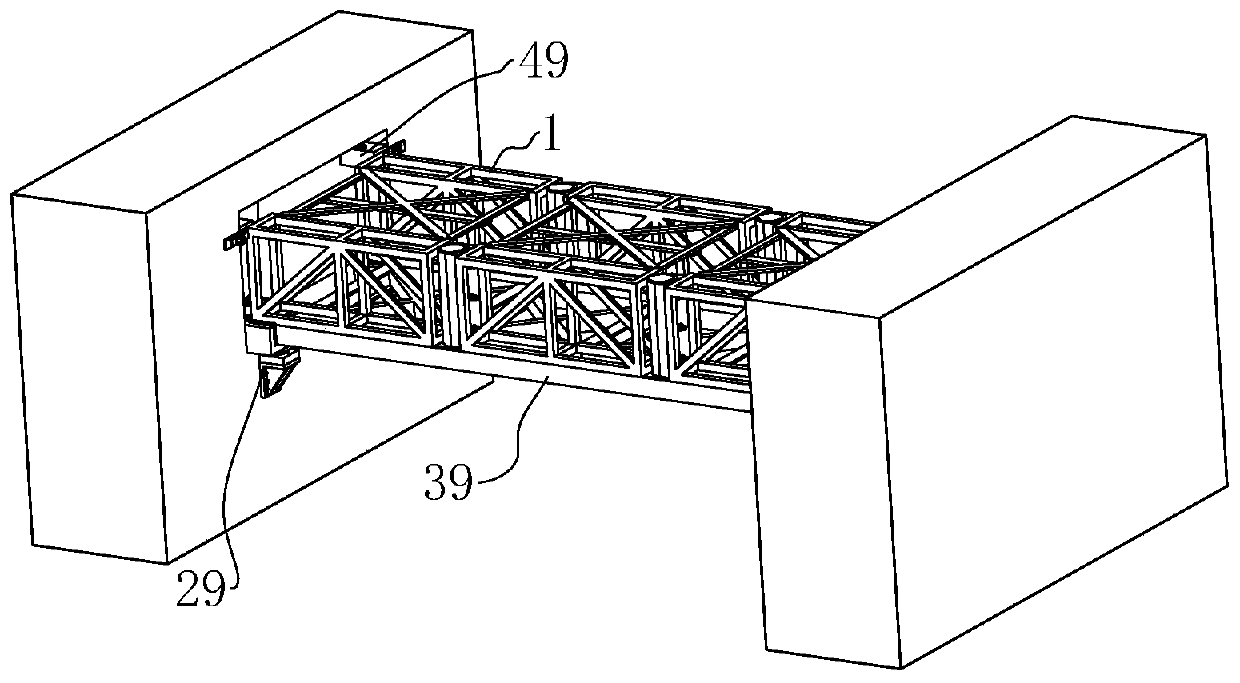
[0047] refer to figure 1 , is a steel structure corridor structure disclosed in this embodiment, including a corridor main body, a connecting slide rail connected between buildings to be connected, and the connecting slide rail is also the bottom of the corridor main body. In this embodiment, All parts are made of steel unless otherwise specified.

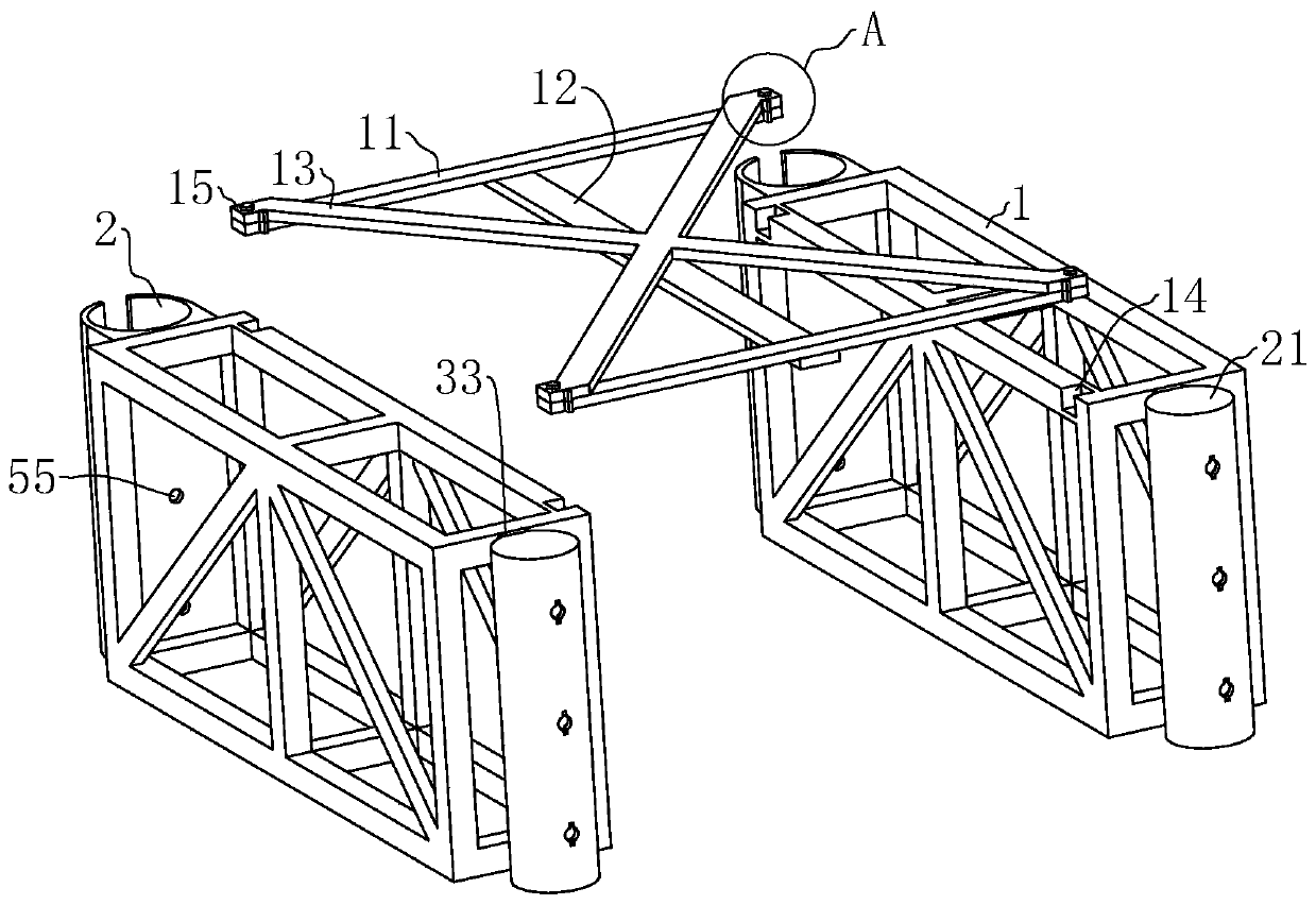
[0048] refer to figure 2 , the main body of the corridor includes several section corridor components, and the corridor components include trusses 1 on both sides in the direction of the building line to be connected, first steel beams 11 arranged between the trusses 1, and connecting first steel beams 11 The second steel beam 12 and the horizontal support 13 connecting the truss 1 and the first steel beam 11 .

[0049] The truss 1 is a parallel chord truss, and the steel structure constituting the truss 1 is ...


PUM


Abstract

The invention relates to the technical field of steel structure corridors, and particularly relates to a steel structure corridor structure and a hoisting construction method. The steel structure corridor structure comprises a corridor main body, a connecting slide rail, connecting assemblies and fixing assemblies, wherein the corridor main body comprises a plurality of corridor components; the connecting slide rail is used for sliding and splicing of the corridor components and comprises connecting parts preset between to-be-connected buildings and a hoisting part connected with the connecting parts; the connecting assemblies are arranged between the corridor components; and fixing components are arranged between the corridor components and the to-be-connected buildings. The steel structure corridor structure has the effects of facilitating installation of the steel structure corridor and making the structure of the steel structure corridor more stable.

Description

technical field [0001] The invention relates to the technical field of steel structure corridors, in particular to a steel structure corridor structure and a hoisting construction method. Background technique [0002] Corridors are beam structures connecting buildings. [0003] Common corridors are made of concrete, which takes a long time, is difficult to construct, and has a heavy structural weight, which makes it inconvenient for construction operations. Therefore, steel structure corridors are becoming more and more popular because of their shorter working hours and lighter structural weight. Having attention. [0004] The existing steel structure corridors are generally connected and assembled on the ground, and then lifted as a whole to be installed between the two buildings, or lifted in stages, and then connected and assembled in the air. The self-weight of the steel structure corridor assembled on the ground is relatively large, which is not conducive to hoisting ...

Claims


Application Information

Patent Timeline
IPC IPC(8): E04B1/00E04G21/00E04G21/16
CPCE04B1/00E04B1/0046E04G21/00E04G21/16
Inventor 蒙绪权黄源军韦小松陈汉长林树荣余冬冬
Owner 广东省构建工程建设有限公司
Learn More