Optical fiber, sealing method for optical fiber end face, connection structure of optical fiber, and optical connector

An end-face sealing, optical fiber technology, applied in the direction of cladding optical fiber, optical waveguide light guide, optical waveguide coupling, etc., can solve the problems of fiber end face cracks and reduce long-term reliability.

Inactive Publication Date: 2008-11-26
HITACHI CABLE
View PDF2 Cites 9 Cited by
  • Summary
  • Abstract
  • Description
  • Claims
  • Application Information

AI Technical Summary

Problems solved by technology

[0007] When connecting with a connector, when the end face of the optical fiber and the end face of the sleeve are ground, the grinding debris will be mixed into the hollow hole. When the connector is repeatedly assembled and disassembled, the abrasive debris entering the hollow hole will be exposed on the end surface of the optical fiber. When the connector is installed, it will cause cracks or defects on the end face of the fiber, reducing its long-term reliability

Method used


Image

  • Optical fiber, sealing method for optical fiber end face, connection structure of optical fiber, and optical connector
  • Optical fiber, sealing method for optical fiber end face, connection structure of optical fiber, and optical connector
  • Optical fiber, sealing method for optical fiber end face, connection structure of optical fiber, and optical connector

Examples


no. 1 approach

[0034]

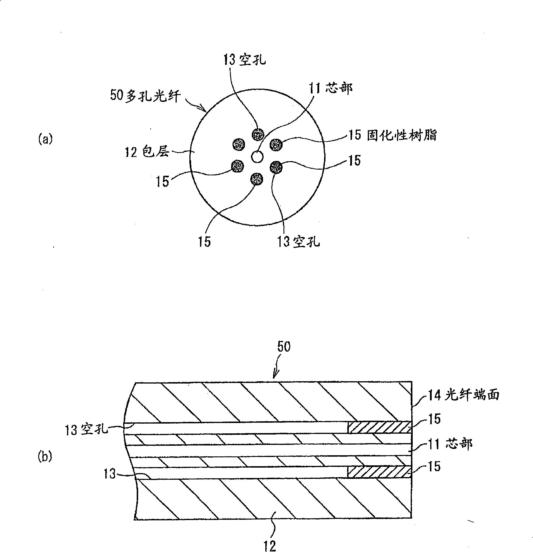
[0035] figure 1 It is the optical fiber in 1st Embodiment of this invention, (a) is a front view, (b) is a side cross-sectional view.

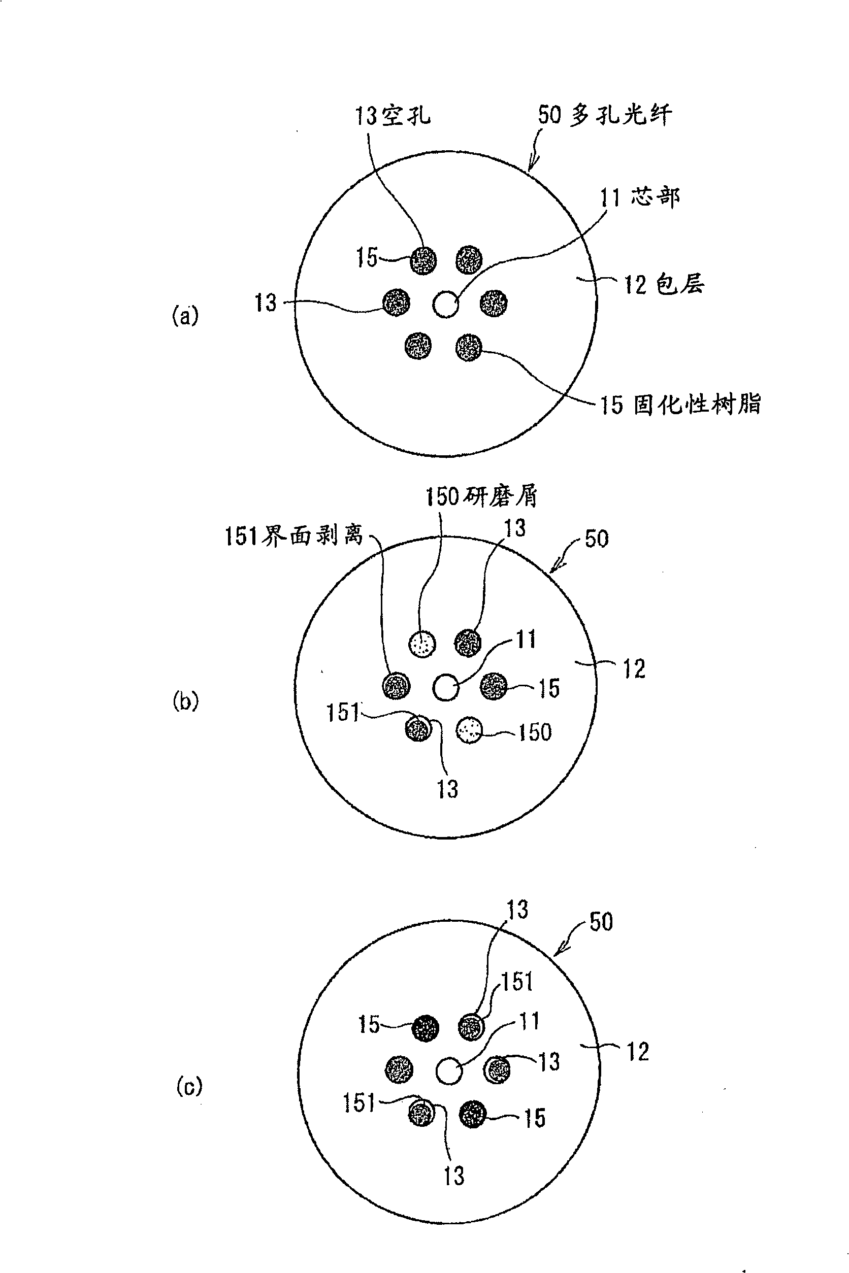
[0036] This optical fiber is a holey fiber 50 composed of a solid core 11, a cladding 12 disposed around the core 11, and a plurality of holes 13 having a refractive index of approximately 1 disposed around the core 11. The holey fiber 50 It also includes a curable resin 15 filled in the cavity 13 of the optical fiber end face 14 . exist figure 1 In (a) and (b), the end face of the core 11 is provided so as to form the same plane as the end face of the holey fiber 50 .

[0037] The curable resin 15 used has a moisture permeability of 0.5 g / cm after curing 2 ·Characteristics below 24h. If the moisture permeability of curable resin 15 is greater than 0.5g / cm 2 ·24h, in an environment with high humidity, dew condensation and the like are likely to occur in the cavity 13, and the loss is likely to increase. Preferably, the moistur...

Embodiment

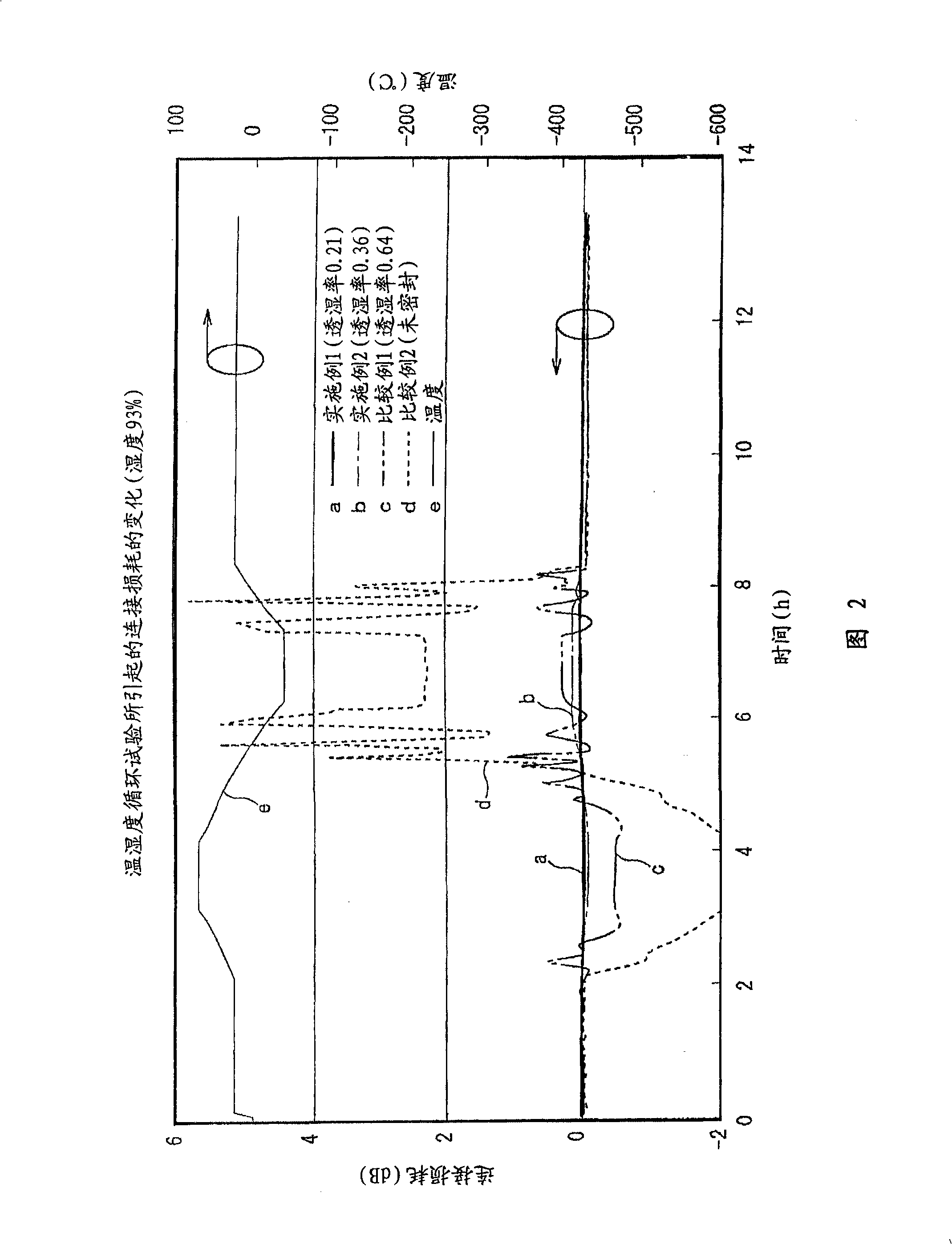
[0049] Next, examples of the present invention will be described. Fig. 2 is a characteristic diagram showing optical fiber connection loss characteristics in the first embodiment.

[0050] As shown in the figure, an SC (Single Coupling) type connector is attached to the end of a holey optical fiber 50 whose cavity 13 is sealed with a curable resin 15, and an optical fiber equipped with a general-purpose SC connector on a normal SMF is connected to the end of the holey optical fiber 50. Changes in the connection loss of the holey fiber 50 when the connection part is placed in a constant temperature bath and subjected to a temperature-humidity cycle test (-40 to +70° C., 93% RH).

[0051] In Figure 2, the moisture permeability of Example 1 is 0.21g / cm 2 24h, the moisture permeability of Example 2 is 0.36g / cm 2 24h, the moisture permeability of Comparative Example 1 is 0.64g / cm 2 24h.

[0052] It can be seen from FIG. 2 that the connection loss of Comparative Example 1 having...


PUM


Abstract

The invention provides an optical fiber with high reliability, sealing method for optical fiber end face, connection structure of optical fiber, and optical connector. The porus optical fiber (50) of the invention is formed by a solid core (11), a clad (12) formed around the core (11), a plurality of holes (13) being formed in the clad with refractive index being 1, and a hardening resin (15) filled in the holes (13) of the optical fiber end face (14). The hardening resin (15) if filled around the optical fiber end face (14) of the plurality of holes (13) and is hardened; the hardening resin (15) having a moisture permeability equal to or less than 0.5 g / cm2.24 hr, or the bonding strength with the glass is 5MPa and the hardness after hardening is the character over 50 expressing by Shore D hardness.

Description

technical field [0001] The invention relates to an optical fiber with a plurality of hollow holes extending longitudinally, a method for sealing the end face of the optical fiber, a connecting structure of the optical fiber and an optical connector. Background technique [0002] With the increase in the speed of optical communication networks and optical signal processing, optical fibers with greater capacity are required. As optical fibers for this purpose, photonic crystals in which a plurality of holes extending along the length of the optical fiber are formed in the cladding around the core. Optical fiber (Photonic Crystal Fiber: PCF) has attracted people's attention. [0003] An example of a total reflection type PCF is a holey fiber (Holey Fiber: HF), which forms a structure that lowers the effective refractive index of the cladding by forming a plurality of holes in the cladding around the Ge-doped core. In this holey fiber, a hole with a refractive index of approxim...

Claims


Application Information

Patent Timeline
Patent Type & Authority Applications(China)
IPC IPC(8): G02B6/02G02B6/25G02B6/38
CPCG02B6/02366G02B6/25G02B6/02385
Inventor 加藤善久铃木香菜子黑泽芳宣大薗和正
Owner HITACHI CABLE
Why Eureka
Try Eureka