
Implantable cardiac assist device

a technology of assist device and cardiac valve, which is applied in the field of therapeutic devices, can solve the problems of heart rhythm loss, problems that can and often do arise, and the heart is a very complex organ that relies on both mechanical and electrical operation, and achieve the effect of preventing device migration during us

Inactive Publication Date: 2006-10-10
COLEMAN EDWARD J DR
View PDF29 Cites 17 Cited by
  • Summary
  • Abstract
  • Description
  • Claims
  • Application Information

AI Technical Summary

Benefits of technology

[0013]It is yet a further object of the present invention to provide a cardiac cup for assisting a heart function that can be installed in its operative position

Problems solved by technology

The human heart is a very complex organ that relies on both mechanical and electrical operation in order to perform properly.
As with any complex mechanism, problems can and often do arise, with the heart.
For example, over time the electrical pathways in the heart (which sequentially cause the atria and ventricles to contract) may fail, thereby causing the heart to lose its rhythm, which is known as arrhythmia.
In that event, the ventricles will contract at improper times, and as a result the output of blood decreases.
In addition, in some failing hearts the muscle of the heart no longer contracts the ventricles to a sufficient extent.
Insufficient ventricular contraction can produce a dangerous reduction in the amount of blood flow.
Thus, manual manipulation of the heart is not a solution to the problem in most cases.
While this device provides an improvement in hemodynamics for a diseased or failing heart, the device is not fully implantable.
Another shortcoming inherent in the prior art devices results from the fact that relatively high pressures are applied almost exclusively to the central portion of the ventricles' outer surfaces.
This causes the heart to deform into an unnatural, generally hourglass, shape and may even eventually cause trauma (e.g., bruises) to the heart, especially if one of the prior art devices is operated for an extended period of time.
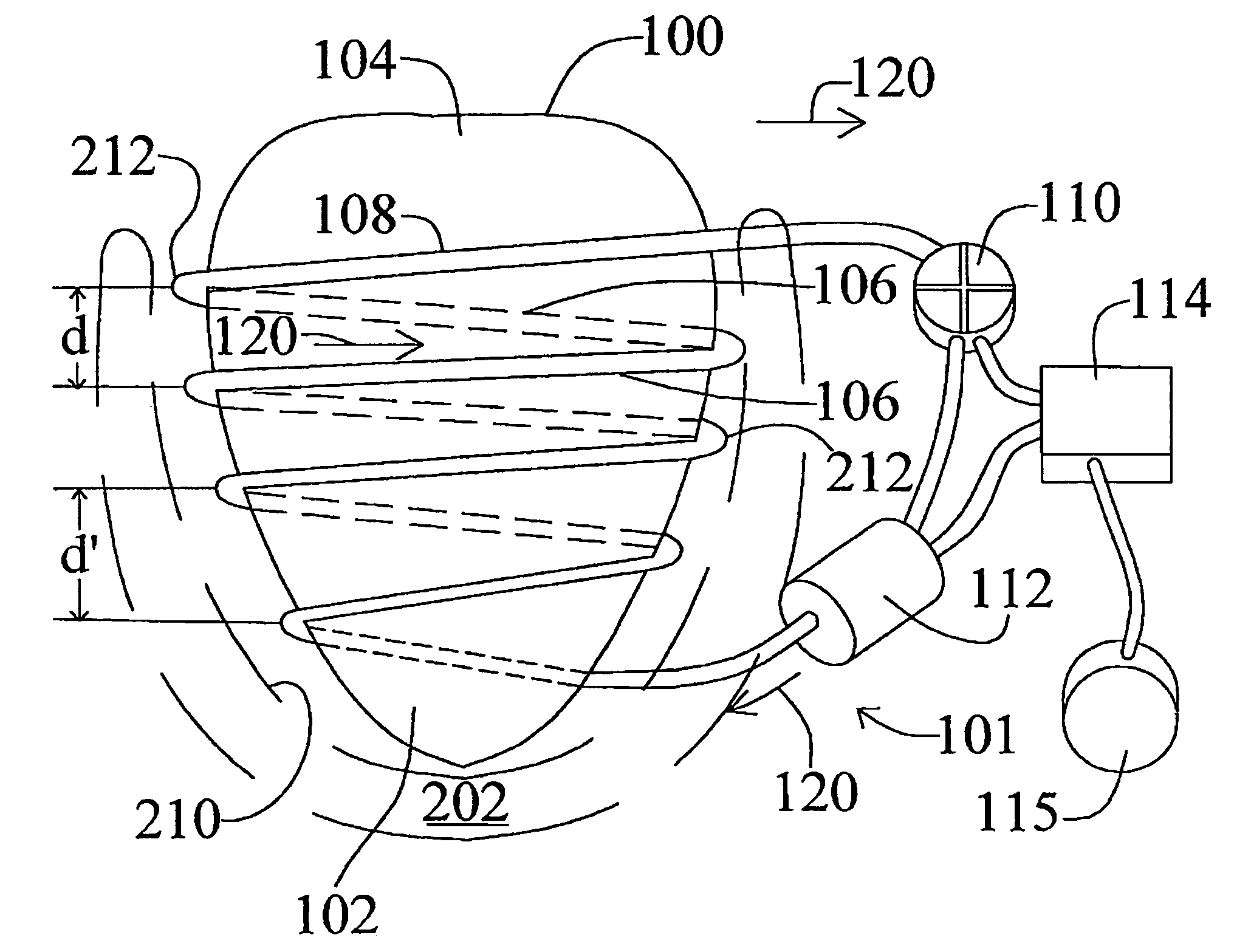
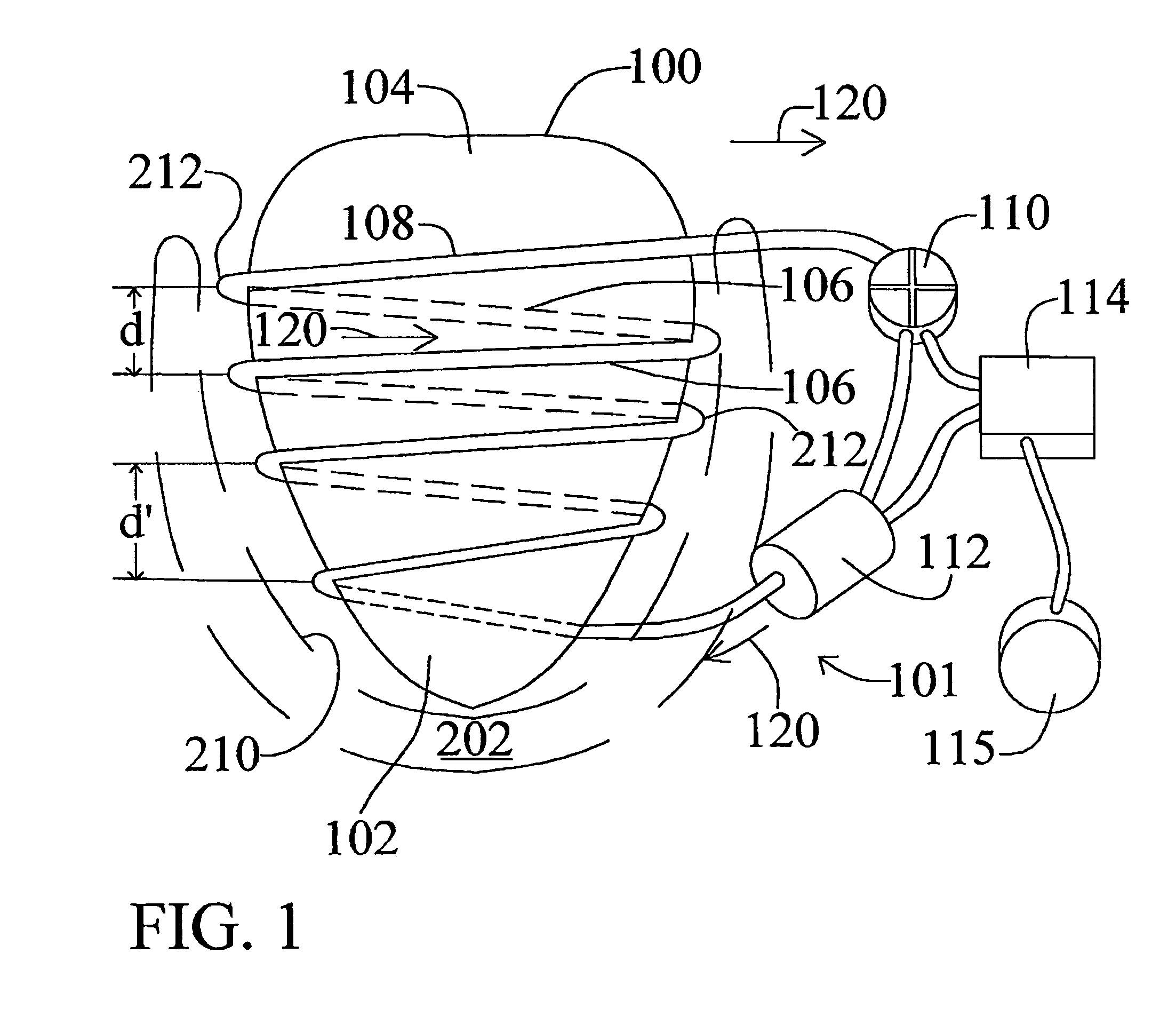
However when normal cardiac output is insufficient to sustain day-to-day activities the present device provides cardiac assist by increasing blood flow by compressing the heart mechanically or hydraulically from the apex or tip of the heart to its base (or top) without abnormal compression of generally the middle portion of the heart.

Method used


Image

  • Implantable cardiac assist device
  • Implantable cardiac assist device
  • Implantable cardiac assist device

Examples


Embodiment Construction

[0027]While the present invention will be described more fully hereinafter with reference to the accompanying drawings, in which particular embodiments are shown, it is to be understood at the outset that persons skilled in the art may modify the invention herein described while still achieving the favorable results of this invention. Accordingly, the description which follows is to be understood as a broad teaching disclosure directed to persons of skill in the appropriate arts and not as limiting upon the present invention.

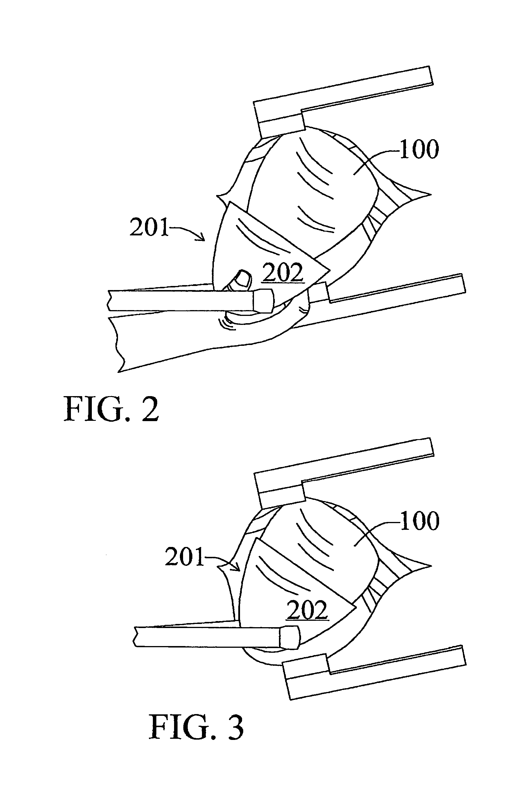
[0028]Thus there is shown in FIG. 1 an embodiment of an apparatus or cardiac assist device 101 of the present invention. A patient's heart 100 is shown schematically. Enveloping or enshrouding heart 100 from its apex 102 to its base 104 is a helically wound length of tubing or a bladder array 106, the tubing segments on the back side of heart 100 being shown in dashed lines. Alternatively, the array 106 could comprise an arrangement, locus, or series of fluidica...


PUM


Abstract

The present invention relates to therapeutic devices to work in conjunction with a diseased or failing heart to satisfy the hemodynamic needs of a patient. More particularly, the invention relates to a fully implantable device for assisting a heart to pump blood by intermittently applying pressure to at least a portion of the ventricular surface of the heart (if not the entire surface), preferably both the atrial and ventricular surfaces, at predetermined or possibly pre-programmed intervals to assist the heart to provide adequate hemodynamic output by sensing demand of the human body. In short, the present invention assists the maintenance of, or reestablishes, the normal contraction sequence of a healthy heart.

Description

CROSS-REFERENCE TO RELATED APPLICATIONS[0001]This application claims priority to U.S. Provisional Patent Application Ser. No. 60 / 464,766, filed Apr. 23, 2003, that application being incorporated herein by reference, in its entirety.STATEMENT REGARDING FEDERALLY SPONSORED RESEARCH OR DEVELOPMENT[0002]Not applicable.FIELD OF THE INVENTION[0003]The present invention relates to therapeutic devices to work in conjunction with a diseased or failing heart to satisfy the hemodynamic needs of a patient. More particularly, the invention relates to a fully implantable device for assisting a heart to pump blood by intermittently applying pressure to at least a portion of the ventricular surface of the heart (if not the entire surface), preferably both the atrial and ventricular surfaces, at predetermined or possibly pre-programmed intervals to assist the heart to provide adequate hemodynamic output by sensing demand of the human body. In short, the present invention assists the maintenance of, ...

Claims


Application Information

Patent Timeline
IPC IPC(8): A61N1/36A61FA61H7/00A61M60/191A61M60/289A61M60/468A61M60/515A61N1/362
CPCA61M1/107A61M1/1086A61M1/122A61M1/1068A61M2205/33A61M2205/3303A61M60/274A61M60/148A61M60/289A61M60/515A61M60/191A61M60/468
Inventor COLEMAN, EDWARD J.COLEMAN, GERARD T.NEILL, WILLIAM T.
Owner COLEMAN EDWARD J DR
Learn More