
Motorized tool with suction and dust collection capacity

a motorized tool and dust collection technology, applied in the direction of portable percussive tools, maintainance and safety accessories, abrasive machine accessories, etc., to achieve the effect of efficient and easy cleaning

Inactive Publication Date: 2006-10-10
VALENTINI GUIDO
View PDF16 Cites 29 Cited by
  • Summary
  • Abstract
  • Description
  • Claims
  • Application Information

AI Technical Summary

Benefits of technology

[0006]The object of the present invention is to provide a system for collecting the dust that is efficient and easy to clean.

Problems solved by technology

A common problem of tools of this type is represented by the elimination of the working dusts, the majority of which are sucked through a duct that takes them outwards.

Method used


Image

  • Motorized tool with suction and dust collection capacity
  • Motorized tool with suction and dust collection capacity
  • Motorized tool with suction and dust collection capacity

Examples


Embodiment Construction

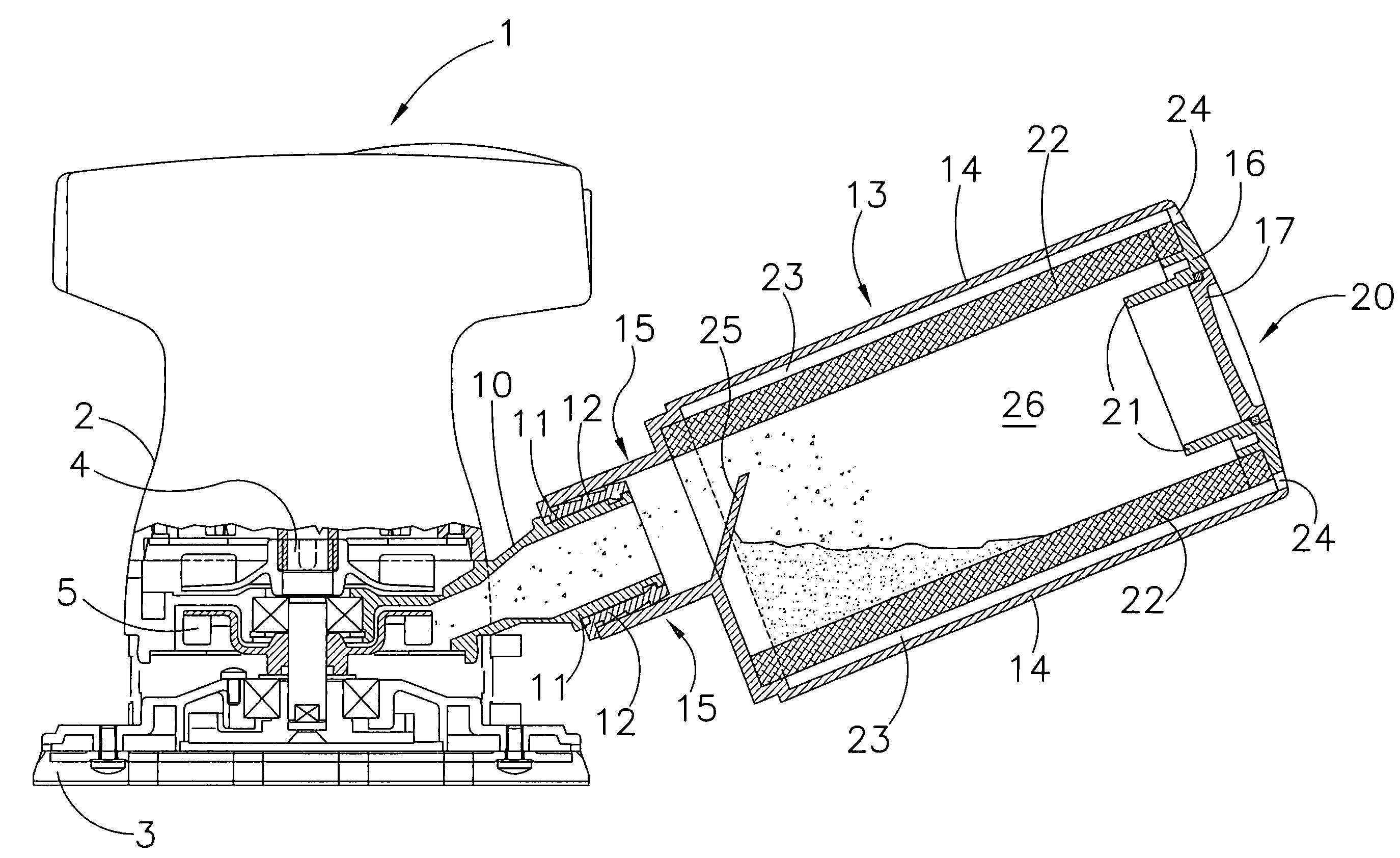
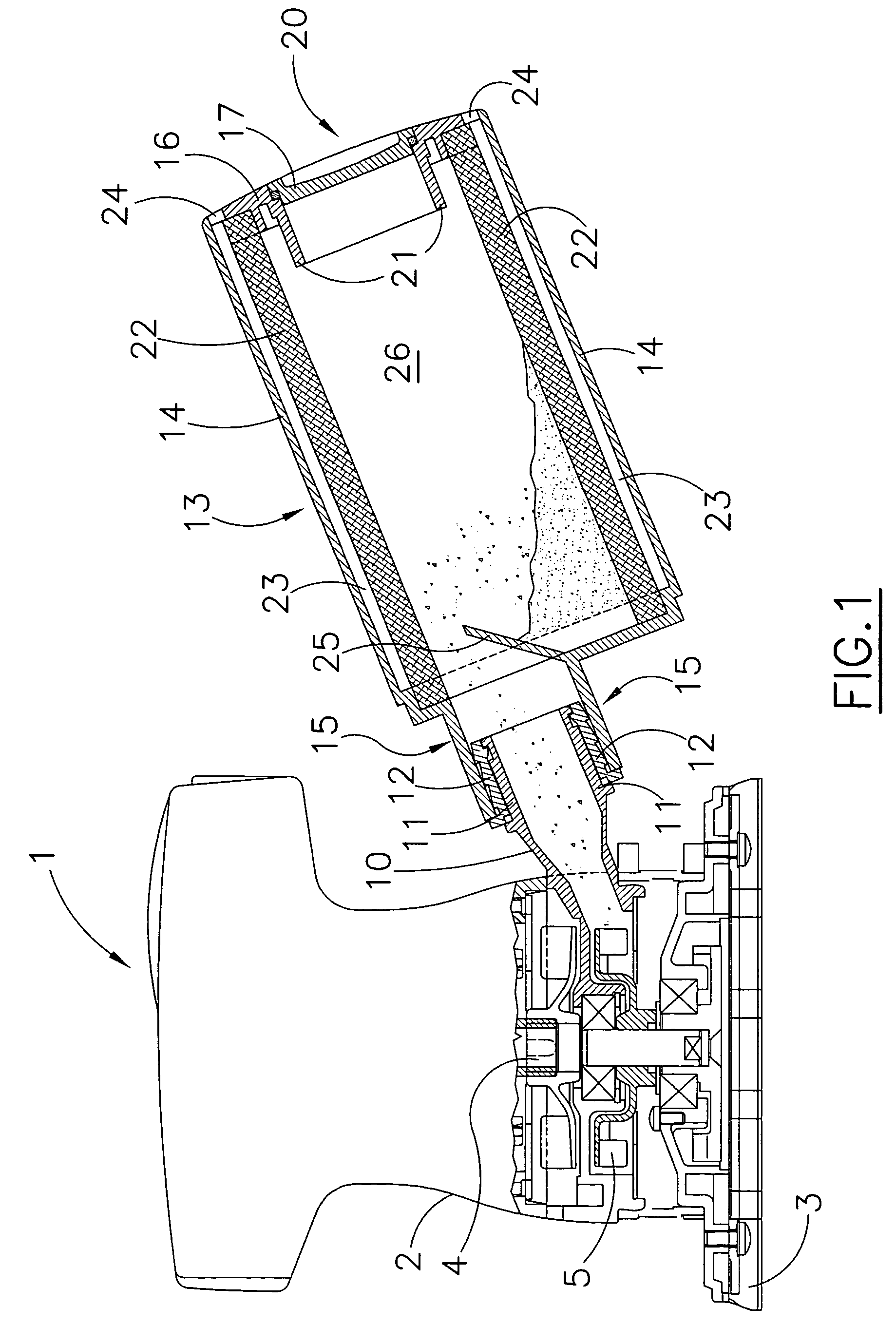
[0020]The tool shown in FIGS. 1–4 is by way of example an orbital sander comprising a working head 1.

[0021]The working head 1 comprises a rigid external casing 2, in which a group of driving mechanisms for an operating disk or plate 3 (or alternatively a rectangular or triangular plate) is housed.

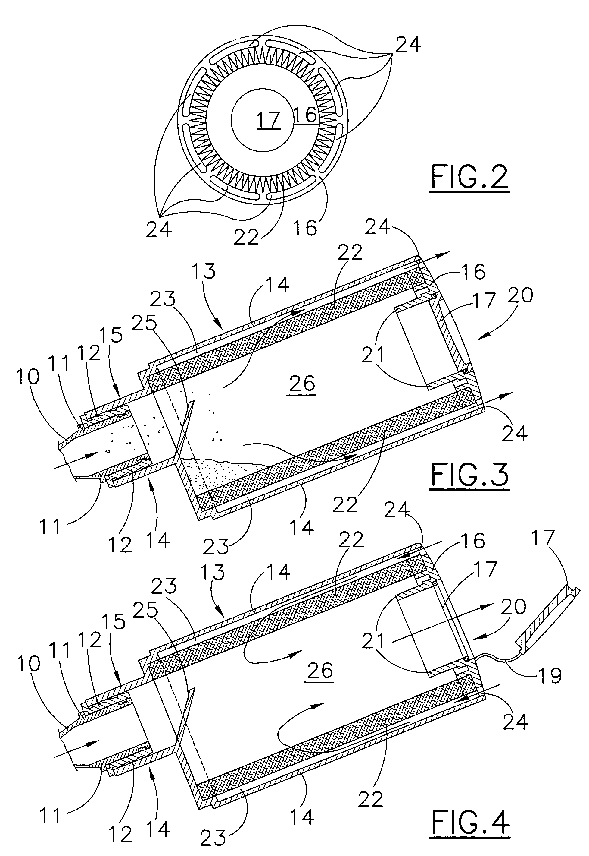
[0022]In turn the driving mechanisms comprise a motor shaft 4 that starts up a fan 5 whose job is to suck in the dust and send it towards a connection tube 10. The connection tube 10 permits the inside of the working head 1 to communicate with the outside environment. The connection tube 10 ends with an outlet 11 preferable fitted with a sealing gasket 12.

[0023]A dust collection receptacle 13 can be connected to the outlet 10. It is preferably composed of a cylindrical receptacle 14 having an outlet 15 placed at one of its ends to be able to connect to the outlet 11. The outlet 15 is eccentric in relation to the central axis of the receptacle 13. At the other end of the receptacle 13 a clos...


PUM

PropertyMeasurementUnit
Timeaaaaaaaaaa
Flow rateaaaaaaaaaa
Shapeaaaaaaaaaa

Abstract

The present invention refers to a motorized tool with suction and dust collection capacity. The tool comprises: means for extracting dust suitable for producing a flow of air; means for collecting dust having a first duct for the entrance of the air, that can be connected separately to said tool, and at least one second duct for the air, connected to the outside environment; said means for collecting dust include a filtering element positioned between said first duct and said second duct. Said filtering element defines an internal space and an external space surrounding said internal space, one of which is in communication with said first duct and the other is in communication with said second duct.

Description

BACKGROUND OF THE INVENTION[0001]The present invention refers to a motorized tool with suction and dust collection capacity.[0002]Motorized tools are known, such as sanders, polishers and so on, in which an operating disk, usually called “plate”, is made to orbit around the axis of a suitably controlled motor shaft.[0003]A common problem of tools of this type is represented by the elimination of the working dusts, the majority of which are sucked through a duct that takes them outwards.[0004]Tools having a suction system directly incorporated into the tool itself are known, where the working dust is conveyed into a special bag for filtering the air located outside the tool. These bags are removable from the tool for replacement and / or cleaning.[0005]The patent application GB 2 343 393 describes a tool including a dust extracting system located inside its receptacle that conveys the dust into a dust collection box. The dust collection box has holes for letting out the air in the uppe...

Claims


Application Information

Patent Timeline
IPC IPC(8): B24B23/00B24B23/04B23Q11/00B24B55/10
CPCB23Q11/0046B23Q11/0057B24B23/00B24B55/10
Inventor VALENTINI, GUIDO
Owner VALENTINI GUIDO
Features
  • Generate Ideas
  • Intellectual Property
  • Life Sciences
  • Materials
  • Tech Scout
  • Unparalleled Data Quality
  • Higher Quality Content
  • 60% Fewer Hallucinations
Learn More