
Identification band using serpentine paths to detect tampering

a technology of identification band and serpentine path, which is applied in the direction of individual entry/exit register, burglar alarm mechanical actuation, instruments, etc., can solve the problem that the band also automatically disables the rfid circui

Inactive Publication Date: 2006-10-10
BARTRONICS HONG KONG
View PDF25 Cites 85 Cited by
  • Summary
  • Abstract
  • Description
  • Claims
  • Application Information

AI Technical Summary

Benefits of technology

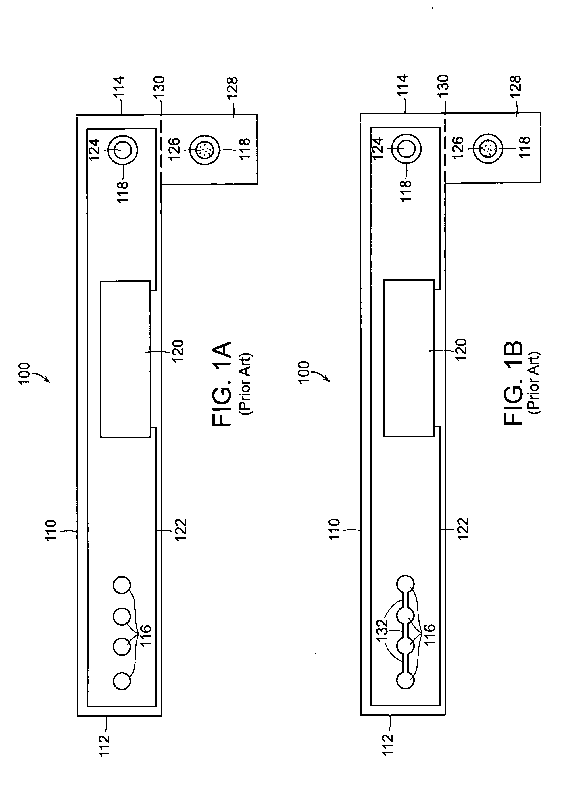
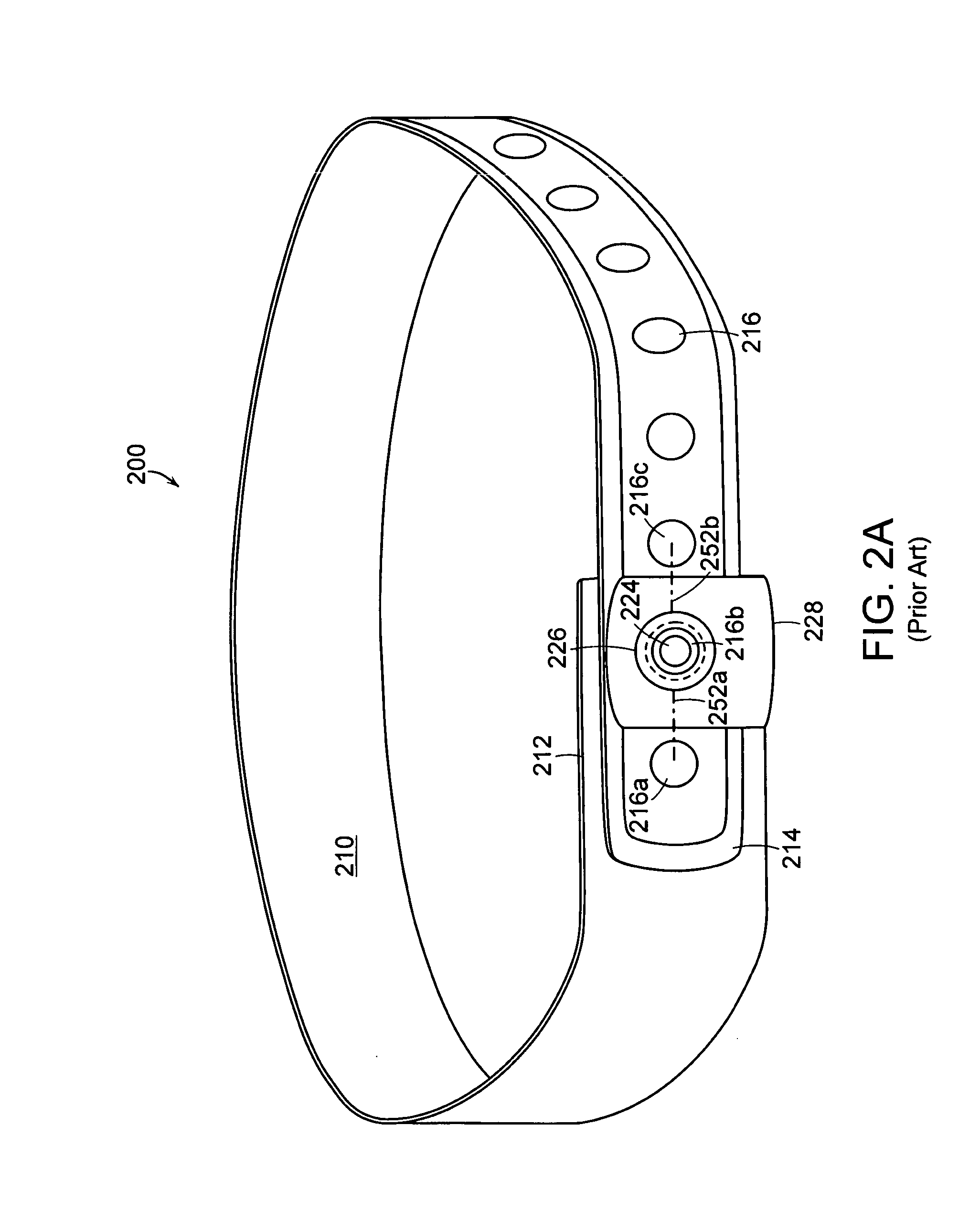
"The present invention provides a tamper-resistant RFID apparatus that becomes permanently disabled upon tampering. The apparatus includes a band of material, an RFID circuit, and an electrically conductive loop disposed in the band. The band of material is such that any severance thereof to remove the band also necessarily disables the RFID circuit. The conductive loop includes a first conductive path and a second conductive path that are electrically isolated from one another, save for at least one electrical connection made preferably by a conductive via between the two surfaces. The RFID circuit can include both an RFID transponder chip and an antenna element. The conductive paths are arranged to together completely encircle each hole such that any attempt to cut or slit the band between adjacent holes necessarily also severs a portion of the conductive loop thereby disabling the RFID circuit. The patent text is applicable in many other form factors and uses, such as for use as an ankle-band or on a piece of luggage."

Problems solved by technology

The band of material is such that any severance thereof to remove the band also necessarily disables the RFID circuit.

Method used


Image

  • Identification band using serpentine paths to detect tampering
  • Identification band using serpentine paths to detect tampering
  • Identification band using serpentine paths to detect tampering

Examples


Embodiment Construction

[0020]A description of preferred embodiments of the invention follows.

[0021]Generally, passive radio frequency identification (RFID) bracelets include circuits containing an antenna and other circuitry that responds to an RF interrogation signal. In response to the RF interrogation signal, a transponder emits an RF signal representative of information pre-stored or pre-programmed into the transponder. For example, the information could include a serial number, the date the bracelet is issued, the date the bracelet expires and will not longer be usable for access, the age status of the wearer, and / or whether the bracelet can be used for purchasing goods or services. Any other desired information, depending on the context in which the bracelet is to be used, may be pre-stored or pre-programmed in the transponder. Information stored on the transponder chip may also be used to access information stored in a database.

[0022]The transponder is electrically connected to and derives power fr...


PUM


Abstract

A tamper-resistant RFID wristband that becomes permanently disabled upon tampering. The wristband includes a plurality of holes for snugly securing the band to a wearer, an RFID circuit, and an electrically conductive loop disposed in the band. The RFID circuit and the conductive loop are electrically coupled to form a series circuit, severance of which disables the wristband. The electrically conductive loop includes a first layer and a second layer that are electrically isolated from one another, save for at least one electrical connection made preferably by a via at the end of the band distal from the antenna element. The first layer encircles the holes in a serpentine path on one layer of the band and the second layer encircles the holes in a complimentary serpentine path on a different layer of the band.

Description

RELATED APPLICATION[0001]This application claims the benefit of U.S. Provisional Application No. 60 / 617,518, filed on Oct. 8, 2004, the entire teachings of which are herein incorporated by reference.BACKGROUND OF THE INVENTION[0002]Bracelets have been used for such things as identification, access control, and age verification for a number of years. For example, various venues may use identification bracelets to quickly and uniquely identify patrons that have access to restricted areas, such as back stage events, alcoholic beverage sales, etc. These bracelets are most often made to be disposable, so that they are inexpensive to produce and easy to use. However, such bracelets are susceptible to misuse and unauthorized use. Some bracelets are easy to remove, yet still function after removal. A bracelet that still serves its purpose after it has been removed provides the opportunity for patrons to exchange and or sell bracelets. This could provide patrons with the opportunity to give ...

Claims


Application Information

Patent Timeline
Patent Type & Authority Patents(United States)
IPC IPC(8): G08B13/12G08B23/00
CPCG06K19/07381G06K19/07762G07C9/00111G08B13/2434G08B13/2474G08B21/0286G07C9/28
Inventor LERCH, JOHN W.GIRVIN, JOSHUA M.NORAIR, JOHN P.MOU, PEIJEN S.
Owner BARTRONICS HONG KONG
Learn More