Methods for driving bistable electro-optic displays, and apparatus for use therein

a technology of electro-optic displays and bistable displays, which is applied in the direction of static indicating devices, instruments, television systems, etc., can solve the problems of inadequate service life of these displays, preventing their widespread use, and not necessarily

Inactive Publication Date: 2006-10-10
E INK CORPORATION
View PDF238 Cites 604 Cited by
  • Summary
  • Abstract
  • Description
  • Claims
  • Application Information

AI Technical Summary

Problems solved by technology

Nevertheless, problems with the long-term image quality of these displays have prevented their widespread usage.
For example, particles that make up electrophoretic displays tend to settle, resulting in inadequate service-life for these displays.
Furthermore, it has now been found, at least in the case of many particle-based electro-optic displays, that the impulses necessary to change a given pixel through equal changes in gray level (as judged by eye or by standard optical instruments) are not necessarily constant, nor are they necessarily commutative.
Although these problems can be reduced or overcome by driving all pixels of the display to one of the extreme states for a substantial period before driving the required pixels to other states, the resultant “flash” of solid color is often unacceptable; for example, a reader of an electronic book may desire the text of the book to scroll down the screen, and may be distracted, or lose his place, if the display is required to flash solid black or white at frequent intervals.
Furthermore, such flashing of the display increases its energy consumption and may reduce the working lifetime of the display.
Furthermore, as will readily be apparent from the foregoing discussion, the drive requirements of bistable electro-optic media render unmodified drivers designed for driving active matrix liquid crystal displays (AMLCD's) unsuitable for use in bistable electro-optic media-based displays.
However, such AMLCD drivers are readily available commercially, with large permissible voltage ranges and high pin-count packages, on an off-the-shelf basis, and are inexpensive, so that such AMLCD drives are attractive for drive bistable electro-optic displays, whereas similar drivers custom designed for bistable electro-optic media-based displays would be substantially more expensive, and would involve substantial design and production time.
Conventional methods for maintaining precise DC-balance require precision-regulated power supplies, precision voltage-modulated drivers for gray scale, and crystal oscillators for timing, and the provision of these and similar components adds greatly to the cost of the display.
However, in practice it is impracticable to effect such internal measurements in an operating display which may contain hundreds of thousands of pixels, and in practice DC balance is measured using an “external” measurement, namely the voltages applied to the electrodes disposed on opposed sides of the electro-optic medium.
Furthermore, even with the addition of such expensive components, true DC balance is still not obtained.
If its remnant voltage is positive, it has been DC unbalanced in the positive direction.
If its remnant voltage is negative, it has been DC unbalanced in the negative direction.
While storing this amount of data poses no problems on a desktop computer, it may present problems in a portable device.
However, as is well known to anyone who has tried to run a word processing program on a computer with inadequate processing power, a one to two second delay in updating a dialog box, in which are displayed the indexing terms being entered by the user, is extremely frustrating and likely to lead to numerous typing errors.
However, such refreshing of the image may give rise to its own problems.
If an image is to be maintained for extended periods by applying refreshing pulses, these pulses need to be of the same polarity as the addressing pulse originally used to drive the relevant pixel of the display to the optical state being maintained, which results in a DC imbalanced drive scheme.
A challenge for achieving accurate gray scale levels in an impulse driven medium is applying the appropriate voltage impulse for achieving the desired gray tone.
However, this is not desirable for an active matrix display, since the frame rate must be increased in order to achieve high pulse width resolution.
A high frame rate increases the power consumption of the display, and puts more strenuous demands on the control and drive electronics.
It is therefore not desirable to operate an active matrix display at frame rates substantially above 60–75 Hz.
The disadvantage of using voltage-modulated techniques is that drivers must have some range of fine voltage control.

Method used


Image

  • Methods for driving bistable electro-optic displays, and apparatus for use therein
  • Methods for driving bistable electro-optic displays, and apparatus for use therein
  • Methods for driving bistable electro-optic displays, and apparatus for use therein

Examples


example

Use of FT Sequences in Cyclic RSGS Waveform

[0429]This Example illustrates the use of FT sequences in improving the optical performance of a waveform designed at achieve 4 gray level (2-bit) addressing of a single pixel display. This display used an encapsulated electrophoretic medium and was constructed substantially as described in Paragraphs [0069] to [0076] of the aforementioned 2002 / 0180687. The single-pixel display was monitored by a photodiode.

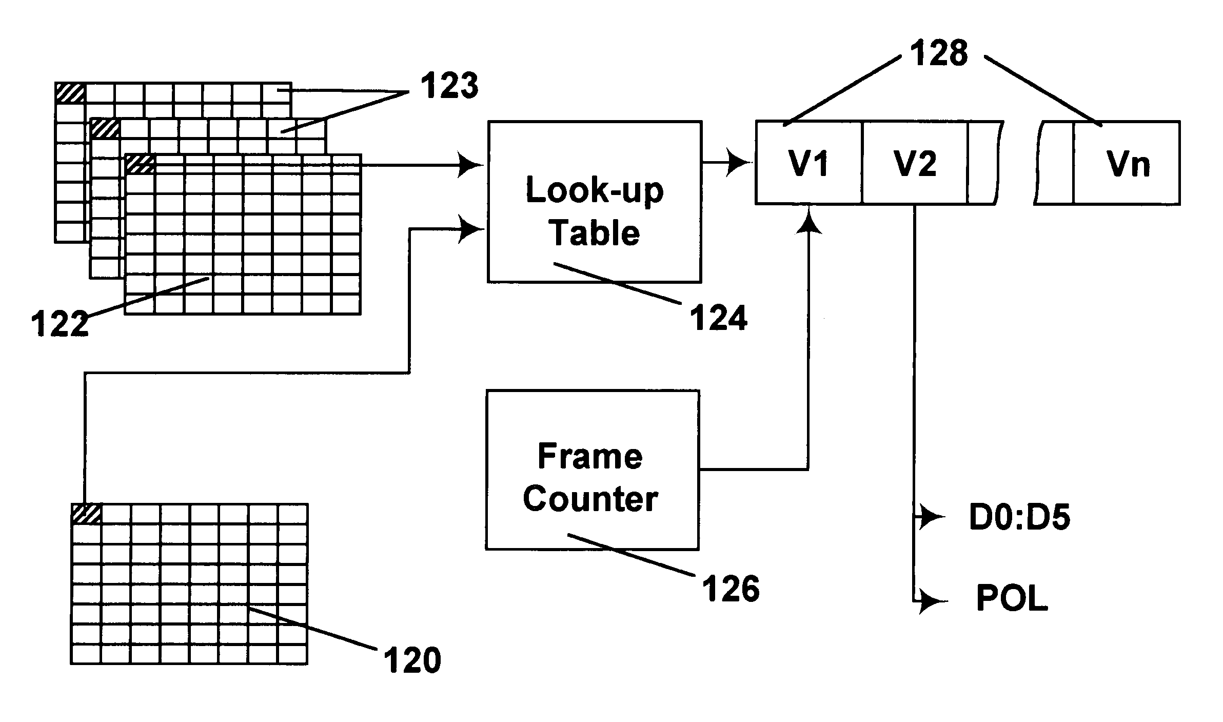
[0430]Waveform voltages were applied to the pixel according to a transition matrix (look-up table), in order to achieve a sequence of gray levels within the 2-bit (4-state) grayscale. As already explained, a transition matrix or look-up table is simply a set of rules for applying voltages to the pixel in order to make a transition from one gray level to another within the gray scale.

[0431]The waveform was subject to voltage and timing constraints. Only three voltage levels, −15V, 0V and +15V were applied across the pixel. Also, in order ...


PUM

PropertyMeasurementUnit
voltageaaaaaaaaaa
voltageaaaaaaaaaa
voltageaaaaaaaaaa

Abstract

A gray scale bistable electro-optic display is driven by storing a look-up table containing data representing the impulses necessary for transitions, storing data representing at least an initial state of each pixel of the display, storing data representing temporal and gray level prior states of each pixel, receiving an input signal representing a desired final state of at least one pixel of the display; and generating an output signal representing the impulse necessary for a transition, as determined from the look-up table, dependent upon the temporal and gray level prior states. Other similar methods for driving such displays are also disclosed.

Description

REFERENCE TO RELATED APPLICATIONS[0001]This application is a continuation in part of application Ser. No. 10 / 065,795, filed Nov. 20, 2002 now U.S. Pat. No. 7,012,600 (Publication No. 2003 / 0137521), which itself claims benefit of the following Provisional Applications: (a) Ser. No. 60 / 319,007, filed Nov. 20, 2001; (b) Ser. No. 60 / 319,010, filed Nov. 21, 2001; (c) Ser. No. 60 / 319,034, filed Dec. 18, 2001; (d) Ser. No. 60 / 319,037, filed Dec. 20, 2001; and (e) Ser. No. 60 / 319,040, filed Dec. 21, 2001. The aforementioned application Ser. No. 10 / 065,795 is also a continuation-in-part of application Ser. No. 09 / 561,424, filed Apr. 28, 2000 (now U.S. Pat. No. 6,531,997), which is itself a continuation-in-part of application Ser. No. 09 / 520,743, filed Mar. 8, 2000 (now U.S. Pat. No. 6,504,524). Application Ser. No. 09 / 561,424 also claims benefit of Application Ser. No. 60 / 131,790 filed Apr. 30, 1999.[0002]This application also claims benefit of the following Provisional Applications: (f) Ser...

Claims


Application Information

Patent Timeline
Patent Type & Authority Patents(United States)
IPC IPC(8): H04N5/14G02F1/167G09G3/20G09G3/34G09G3/38
CPCG02F1/167G09G3/2011G09G3/344G09G3/38G09G3/2018G09G2300/08G09G2310/02G09G2310/0254G09G2310/027G09G2310/04G09G2310/06G09G2310/061G09G2310/063G09G2310/065G09G2310/068G09G2320/0204G09G2320/0247G09G2320/0252G09G2320/0285G09G2320/04G09G2320/041G09G2320/043G09G2330/021G09G2340/16
Inventor AMUNDSON, KARL R.ZEHNER, ROBERT W.KNAIAN, ARA N.ZION, BENJAMIN
Owner E INK CORPORATION
Why Eureka
Try Eureka