Magnetic transfer apparatus

Inactive Publication Date: 2006-10-10
FUJIFILM HLDG CORP +1
View PDF2 Cites 6 Cited by
  • Summary
  • Abstract
  • Description
  • Claims
  • Application Information

AI Technical Summary

Benefits of technology

[0020]In the magnetic transfer apparatus in accordance with the present invention, by virtue of the locator mechanism which locates the holder at least in a direction perpendicular to the central axis of the holder, the holder can be accurately and easily relocated on the holder support portion after it is once removed therefrom, whereby workability in maintenance such as changing the holders or cleaning the master information carrier can be improved and a stabilized magnetic transfer accuracy can be ensured.
[0021]When the locator mechanism comprises a sliding guide or a rolling guide employed at the contact portion between the holder and the holder support portion, the holder locating accuracy is improved and the locator mechanism can be high in rigidity and excellent in durability, which is advantageous also from the viewpoi

Problems solved by technology

That is, when there is defect in close contact between the slave medium and the master information carrier, there is generated an area where no magnetic transfer occurs, which results in a signal missing in the information transferred to the slave medium and deterioration in quality of the signal transferred.
When the transferred information is a servo signal, the signal missing results in an unsatisfactory tracking and deteriorates the reliability of the slave medium.
A problem in the magnetic transfer is to accurately transfer the magnetization patter about the axis of rotation of the slave medium.
Conventionally since the holder has been fixed to the magnetic transfer apparatus body by bolts, mounting and demounting the holder on and from the magnetic transfer apparatus body is not good in workability, and adhesion to the master information carr

Method used


Image

  • Magnetic transfer apparatus
  • Magnetic transfer apparatus
  • Magnetic transfer apparatus

Examples


Example

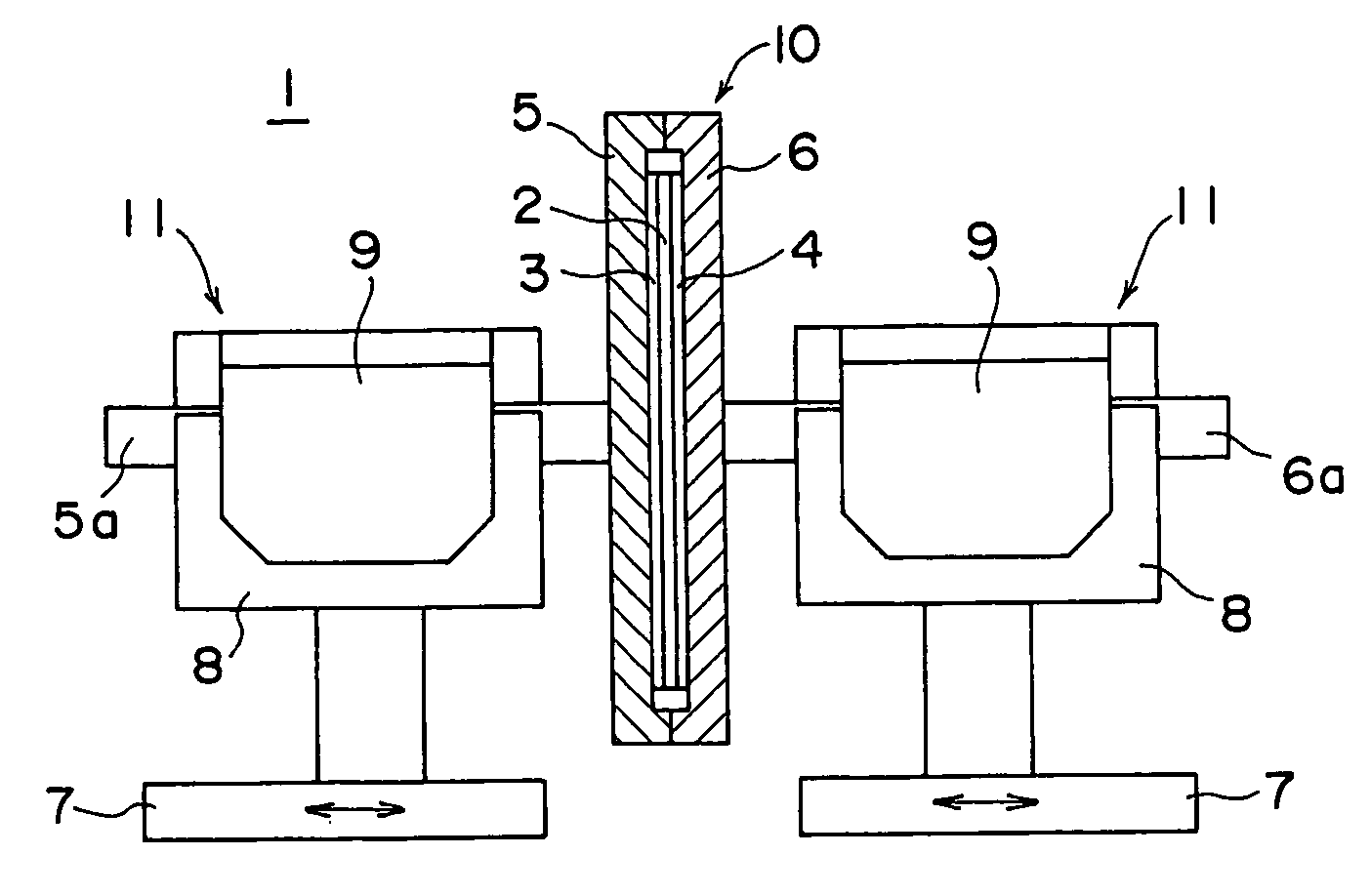
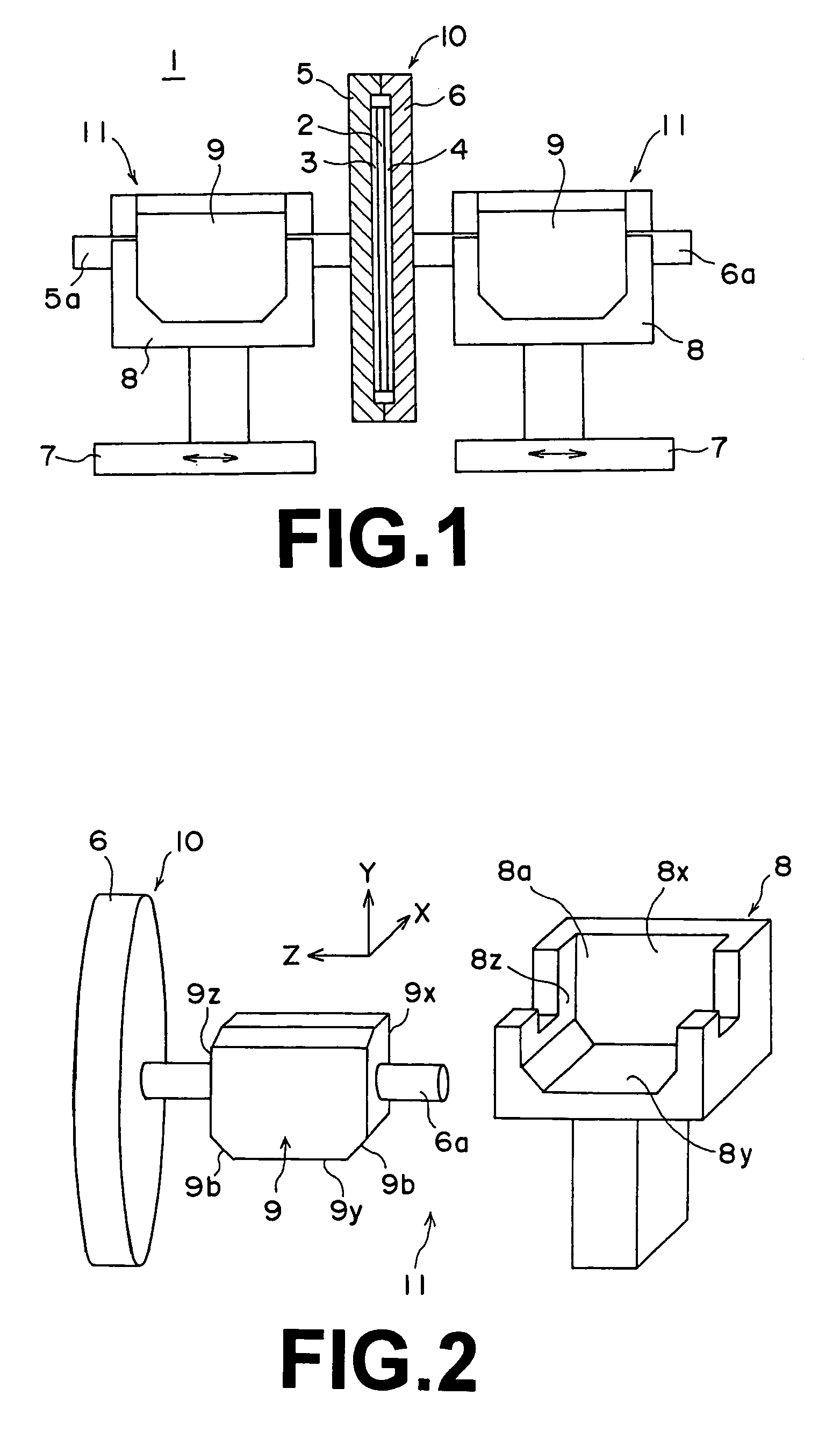
[0031]In FIG. 1, a magnetic transfer apparatus 1 comprises a transfer holder 10 formed by a pair of holder halves, a first holder half 5 and a second holder half 6. The first and second holder halves 5 and 6 are closed to form an air-tight space therebetween, in which a pair of master information carriers, a first master information carrier 3 and a second master information carrier 4 carrying thereon information (e.g., a servo signal) to be transferred to a slave medium 2 and the slave medium 2 are placed so that the master information carriers 3 and 4 are brought into close contact with opposite sides of the slave medium 2.

[0032]Though not shown in detail, the first holder half 5 holds the first master information carrier 3 and the slave medium 2 on its inner surface under a suction and the second holder half 6 holds the second master information carrier 4 on its inner surface under a suction.

[0033]A first support shaft 5a is erected from the outer side of the first holder half 5 a...


PUM


Abstract

A magnetic transfer apparatus magnetically transfers information carried by a master information carrier to a slave medium held in close contact with the master information carrier by a holder disposed on the holder support portion of a magnetic transfer apparatus. The holder is formed by a pair of halves movable toward and away from each other, and a transfer magnetic field is applied to the master information carrier and the slave medium held in close contact with each other by the holder. A locator mechanism is provided between the holder support portion and the holder and locates the holder at least in a direction perpendicular to the central axis of the holder.

Description

BACKGROUND OF THE INVENTION[0001]1. Field of the Invention[0002]This invention relates to a magnetic transfer apparatus in which information carried by a master information carrier is magnetically transferred to a slave medium by setting the master information carrier and the slave medium in a transfer holder to bring them into close contact with each other and setting the transfer holder in a holder supporting portion of the magnetic transfer apparatus.[0003]2. Description of the Related Art[0004]This invention is applied to a magnetic transfer in which a master information carrier having an irregularity pattern or an embedded pattern representing information to be transferred and covered with a magnetic layer (a patterned master) is held in close contact with a slave medium having a magnetic recording area and a transfer magnetic field is applied to the master information carrier and the slave medium in this state, thereby recording a magnetization pattern corresponding to the inf...

Claims


Application Information

Patent Timeline
IPC IPC(8): G11B5/86G11B23/00
CPCG11B5/865G11B23/0021
Inventor KAMATANI, AKITO
Owner FUJIFILM HLDG CORP
Why Eureka
Try Eureka