Method of displaying dynamically scattering vector of X-ray diffraction

a dynamic scattering vector and x-ray technology, applied in the direction of material analysis, material analysis using wave/particle radiation, instruments, etc., can solve the problem that the apparatus capable of realizing such a technology has not yet been found

Inactive Publication Date: 2006-10-10
RIGAKU CORP
View PDF5 Cites 13 Cited by
  • Summary
  • Abstract
  • Description
  • Claims
  • Application Information

AI Technical Summary

Benefits of technology

[0008]A method according to the present invention comprises a step of displaying two-dimensionally or three-dimensionally a dynamic motion and tracks of the tip location of a scattering vector of X-ray diffraction under changing measuring conditions on a display screen which represents the reciprocal space of a sample crystal. This invention has an advantage that the tip location of the scattering vector can be seen dynamically and the X-ray diffraction phenomenon under changing measuring conditions can be readily understood, effecting easy consideration of the measuring conditions and easy evaluation of the measured results.
[0010]The dynamic display method is usable for a dynamic simulation, in which (1) an operator enters measuring conditions into a measuring-condition setting device, (2) a control device acquires the measuring conditions, and (3) the control device puts the virtual scattering vector in motion on a display screen based on the measuring conditions acquired. The dynamic display method is for showing neither the movement of a visible X-ray detector nor a visible sample but the motion of the scattering vector in the reciprocal space dynamically, the scattering vector being invisible actually but representing importantly the nature of the X-ray diffraction phenomenon. The method of the present invention is therefore best suited for the study of measuring conditions. Furthermore, the dynamic display method is effective in showing the X-ray diffraction phenomenon visually for persons not familiar with the X-ray diffraction.
[0013]It is also useful to superimpose the locations of the reciprocal lattice points on the tracks. The X-ray diffraction principle suggests that when the tip location of the scattering vector coincides with any reciprocal lattice point, an X-ray diffraction phenomenon occurs at the crystal lattice plane corresponding to the reciprocal lattice point. Therefore, observing the superposition of the locations of the reciprocal lattice points on the tracks makes it possible to determine whether or not X-ray diffraction occurs on the tracks.

Problems solved by technology

An apparatus realizing such technology, however, has not been found.

Method used


Image

  • Method of displaying dynamically scattering vector of X-ray diffraction
  • Method of displaying dynamically scattering vector of X-ray diffraction
  • Method of displaying dynamically scattering vector of X-ray diffraction

Examples


Embodiment Construction

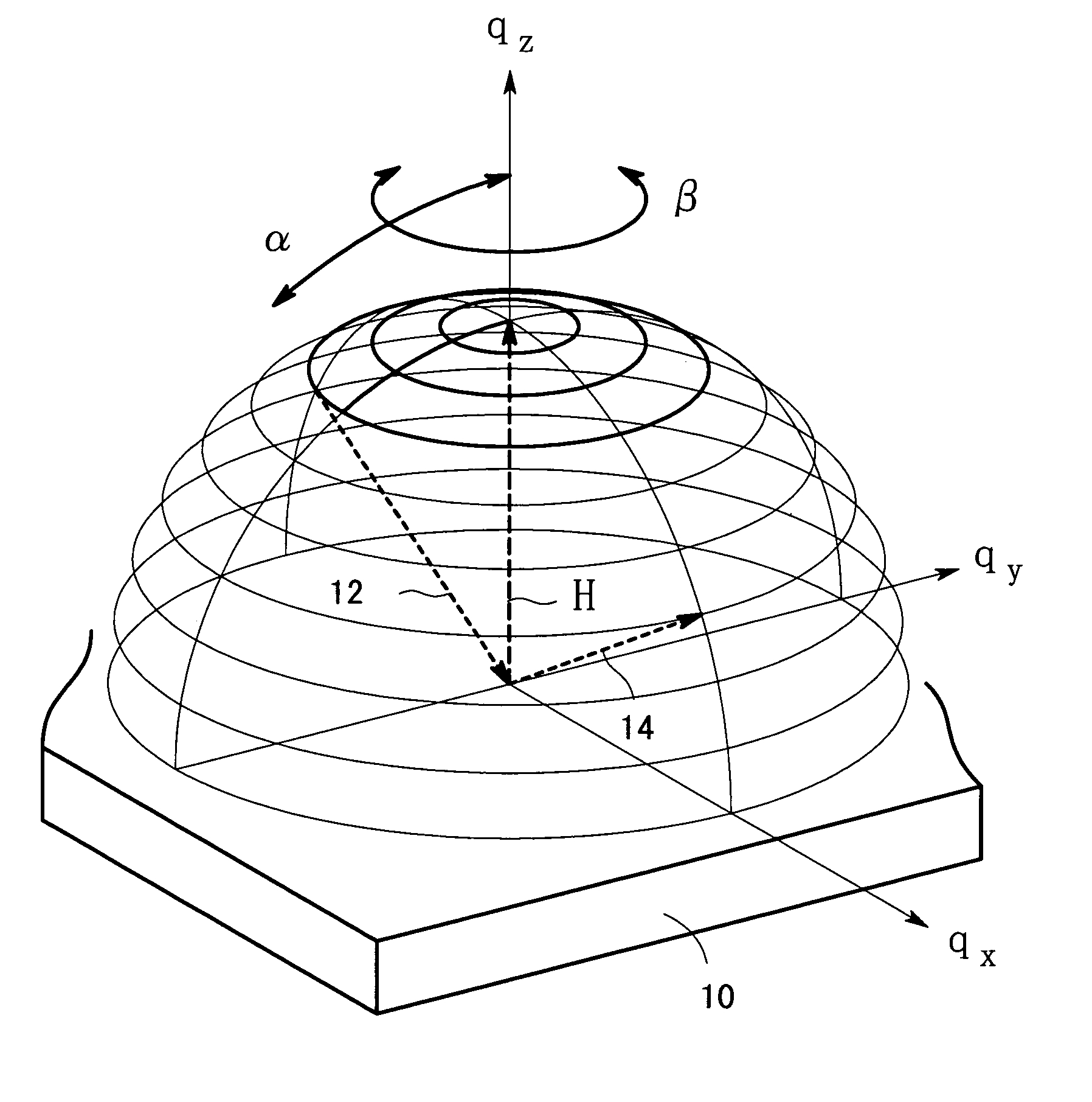
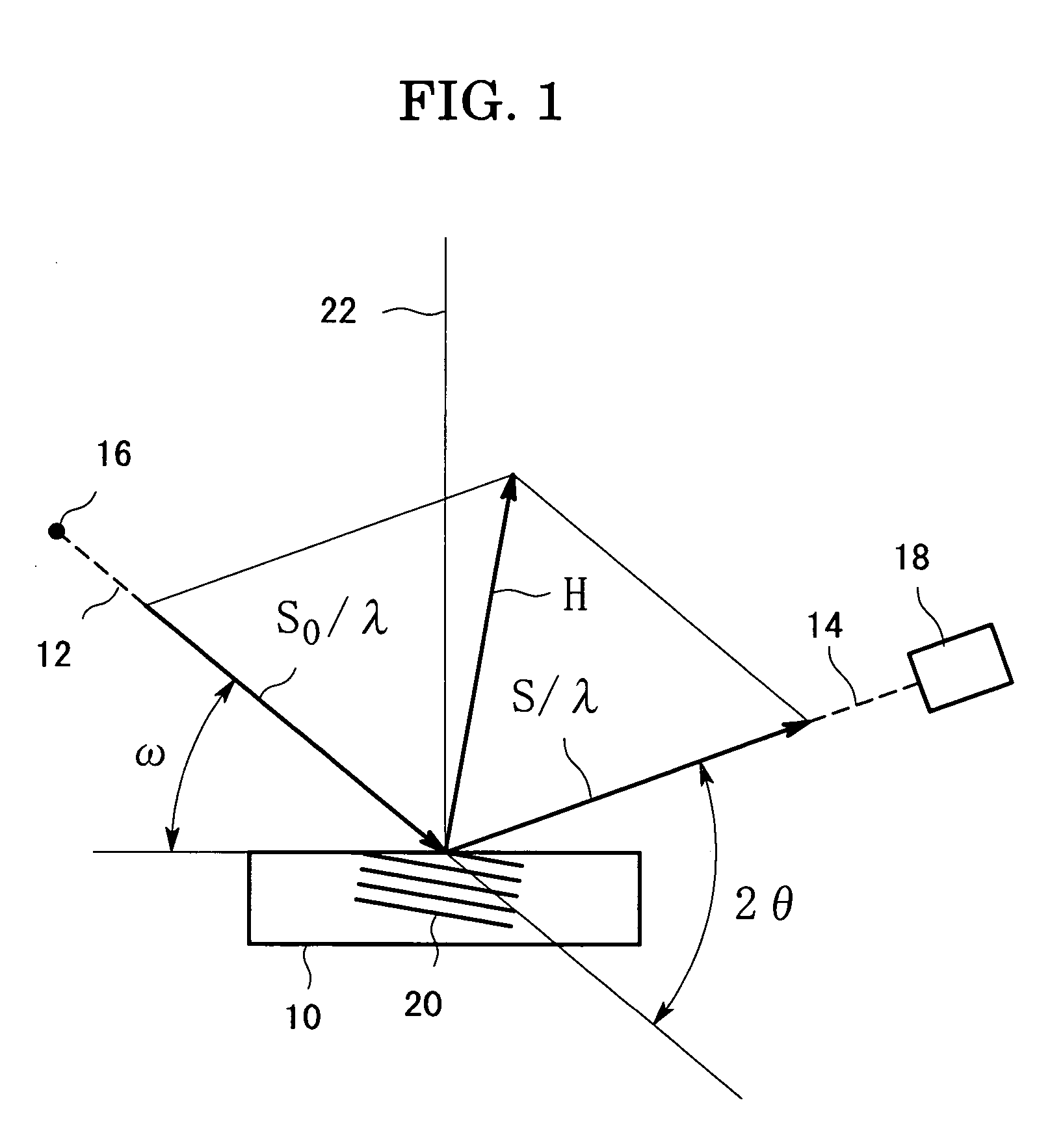
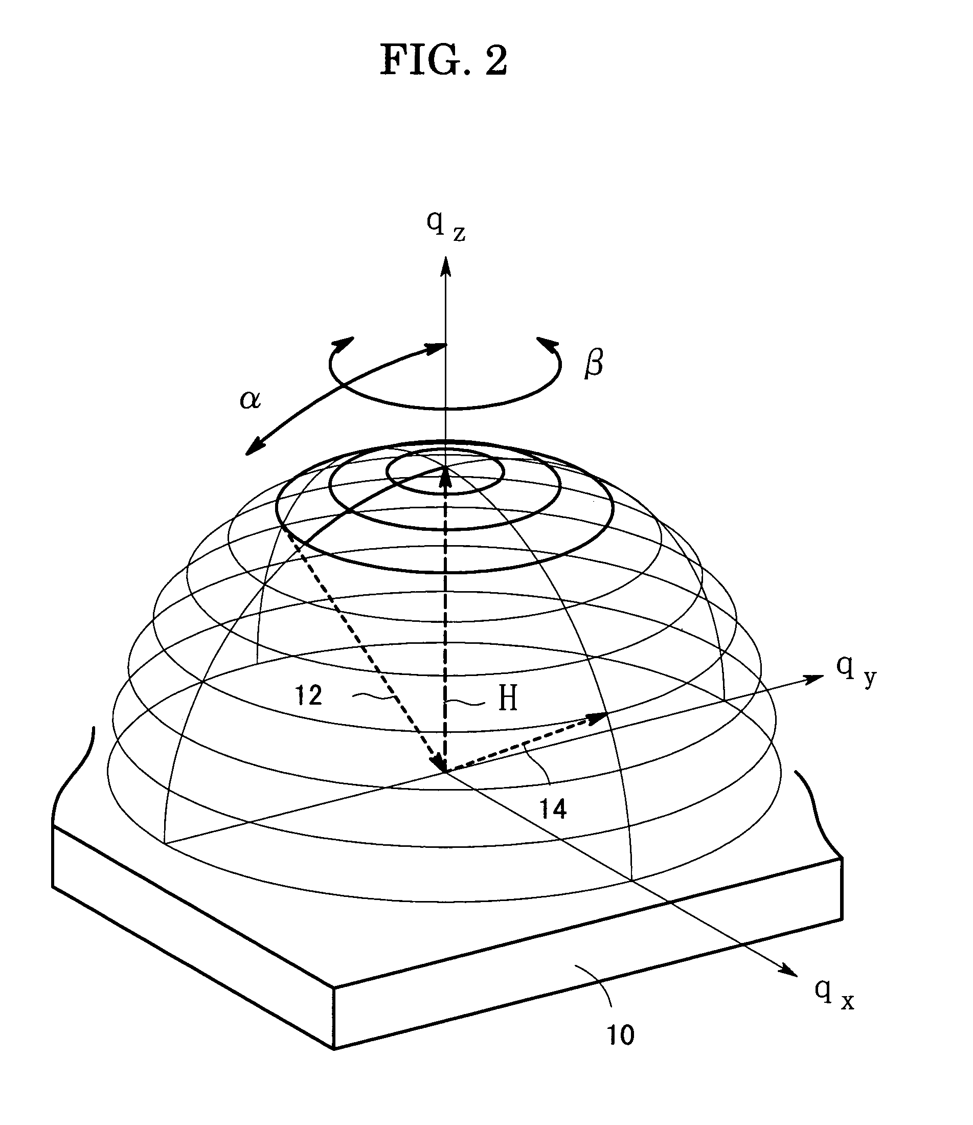
[0023]An embodiment of the present invention will be described with reference to the drawings. First of all, the scattering vector will be explained. FIG. 1 is a view for explaining the scattering vector H of X-ray diffraction, in which an X-ray 12 is incident on the surface of a sample 10, and a diffracted X-ray 14 goes out of the sample surface. An angle of the incident X-ray 12 to the surface of the sample 10 is referred to as an incident angle which is denoted by ω, and an angle of the diffracted X-ray 14 to the incident angle 12 is referred to as a diffraction angle which is denoted by 2θ. In the X-ray diffraction measurement, the incident X-ray 12 comes from an X-ray source 16, and the diffracted X-ray 14 is to be detected by an X-ray detector 18.

[0024]An X-ray diffraction phenomenon will be explained with the use of the reciprocal space of the crystal which makes up the sample 10. A unit vector S0 is taken as extending in the direction of the incident X-ray 12, and another un...


PUM

PropertyMeasurementUnit
diffraction angle 2θaaaaaaaaaa
angleaaaaaaaaaa
angleaaaaaaaaaa

Abstract

The scattering vector of X-ray diffraction is dynamically displayed on a screen. A dynamic motion and tracks of the tip location of the scattering vector of X-ray diffraction is displayed two-dimensionally or three-dimensionally under changing measuring conditions on a screen which represents the reciprocal space of a sample crystal. The tip location of the scattering vector can be seen dynamically and the X-ray diffraction phenomenon under changing measuring conditions can be readily understood, effecting easy consideration of the measuring conditions and easy evaluation of the measured results.

Description

BACKGROUND OF THE INVENTION[0001]1. Field of the Invention[0002]The present invention relates to a method of dynamically displaying a motion of the tip location of a scattering vector of X-ray diffraction.[0003]2. Description of the Related Art[0004]The scattering vector of X-ray diffraction is a concept which has been introduced to explain theoretically the X-ray diffraction phenomenon. The scattering vector is helpful in understanding the X-ray diffraction phenomenon. The scattering vector is indeed useful in considering measuring conditions and in interpreting measured results in the actual X-ray diffraction measurement procedure. Although the scattering vector is a useful concept as described above, its direction and magnitude are invisible because the scattering vector is an imaginary existence which is defined by the relative location among an X-ray source, a sample and an X-ray detector.[0005]A certain prior art has been developed which makes it possible to display such scatt...

Claims


Application Information

Patent Timeline
Patent Type & Authority Patents(United States)
IPC IPC(8): G01N23/201G01N23/20G01N23/205G06F19/00
CPCG01N23/2055
Inventor OZAWA, TETSUYAYAMAGUCHI, SUSUMUKAKEFUDA, KOHJI
Owner RIGAKU CORP
Why Eureka
Try Eureka