Bridged cryptographic VLAN

Inactive Publication Date: 2006-10-10
MICROSOFT TECH LICENSING LLC
View PDF15 Cites 23 Cited by
  • Summary
  • Abstract
  • Description
  • Claims
  • Application Information

AI Technical Summary

Benefits of technology

[0010]The invention comprises three extensions of the IEEE 802.1Q VLAN bridge model (see IEEE Std 802.1Q-1998, IEEE Standards for Local and Metropolitan Area Networks: Virtual Bridged Local Area Networks). The first extension is the cryptographic separation of VLANs over trunk links. A new LAN segment type, referred to herein as the encapsulated segment type, is introduced. All frames on such a segment are encapsulated according to an encryption and authe

Problems solved by technology

Various limitations are encountered with the current state of VLAN art.
O

Method used


Image

  • Bridged cryptographic VLAN
  • Bridged cryptographic VLAN
  • Bridged cryptographic VLAN

Examples


example 1

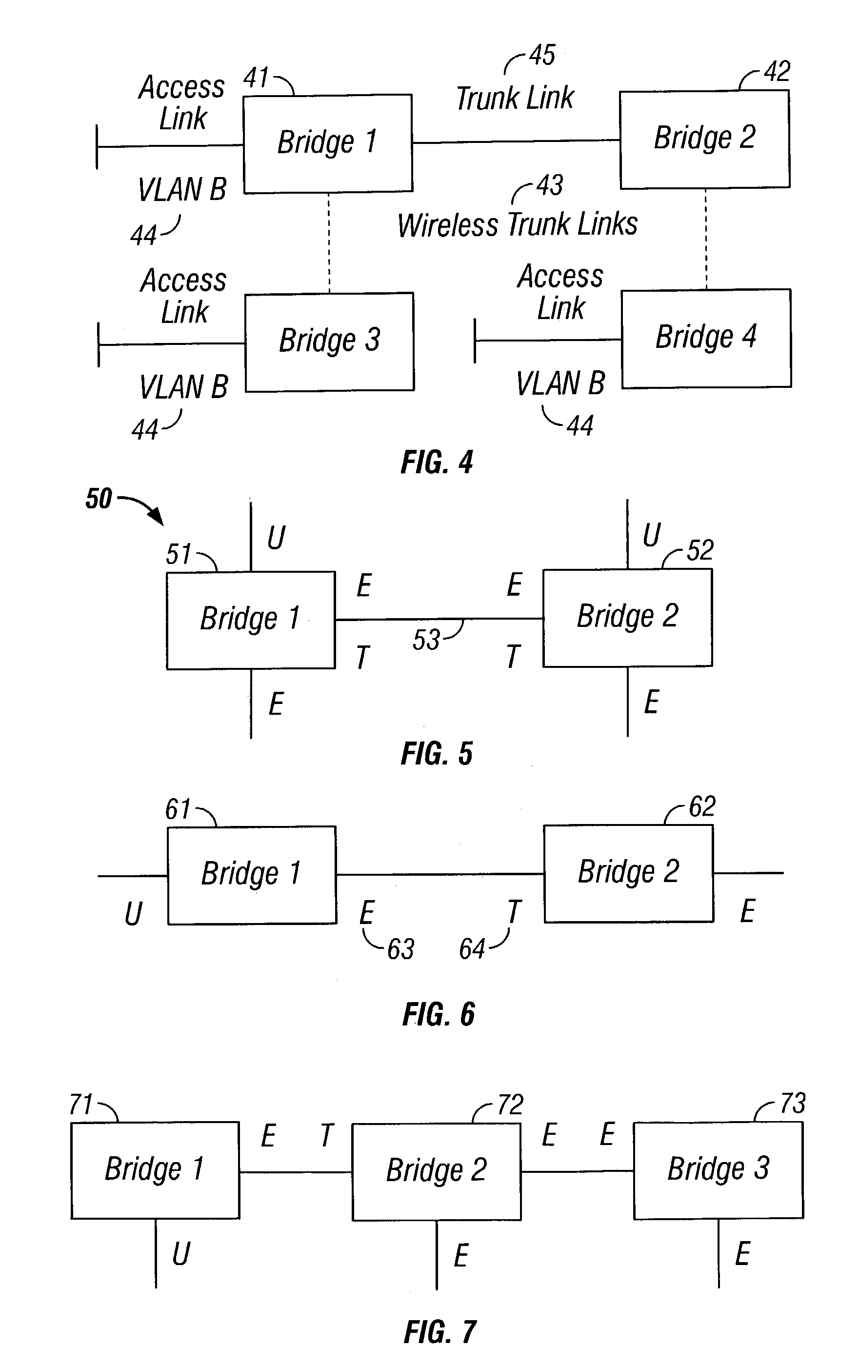
[0066]Consider bridging a single VLAN. Each access port therefore is assumed to belong to this VLAN. Thus, VLAN labeling of ports is omitted in the examples. Instead, the outbound trunk ports are labeled with LAN segment types, i.e. T (tagged), U (untagged), and E (encapsulated). If an outbound port is labeled with U, for example, then the port belongs to the untagged set of the VLAN.

[0067]Initially, every access port is labeled according to the kind of set to which the port belongs for the VLAN. Trunk ports are initially unlabeled. It is the job of TPP to infer labels for them. FIG. 5 shows a bridging of a VLAN 50 where two bridges 51, 52 are connected by a trunk 53. Each bridge has two access ports. Because each bridge has both untagged and encapsulated access ports, TPP infers that both outbound ports of the trunk belong to the tagged and encapsulated sets of the VLAN. Each inbound port also belongs to these sets.

[0068]Each outbound port is a member of the tagged set per rule TPP...

example 2

[0069]In FIG. 6, Bridge 1 (61) has an untagged access port and Bridge 2 (62) has an encapsulated access port. Therefore, the outbound port 63 of Bridge 1 is a member of the encapsulated set per rule TPP-E (a) whereas the outbound port 64 of Bridge 2 is a member of the tagged set per rule TPP-T (a).

example 3

[0070]FIG. 7 illustrates a purely encapsulated trunk link. All frames over the link are encapsulated, however, no encryption is done at Bridges 2 or 3.

[0071]FIG. 8 shows the TPP message exchange between Bridges 1 (71), 2 (72), and 3 (73) when Bridge 1 (71) of FIG. 7 initiates an announce frame for the VLAN, which we assume for the example is named “B”.


PUM


Abstract

The invention comprises three extensions of the IEEE 802.1Q VLAN bridge model. The first extension is the cryptographic separation of VLANs over trunk links. A LAN segment type referred to as an encapsulated LAN segment is introduced. All frames on such a segment are encapsulated according to an encryption and authentication code scheme. The second extension is the division of a trunk port into inbound and outbound ports. The third extension is a protocol that automatically infers for each outbound port in a bridged VLAN, a set of LAN segment types for the port that minimizes the number of transfers between encapsulated and unencapsulated segments required to transport a frame in the bridged VLAN.

Description

CROSS-REFERENCE TO RELATED APPLICATIONS[0001]This application is a Continuation-in-Part of U.S. patent application Ser. No. 10 / 057,566, filed Jan. 25, 2002.BACKGROUND OF THE INVENTION[0002]1. Technical Field[0003]The invention relates to VLANs. More particularly, the invention relates to a bridged cryptographic VLAN.[0004]2. Description of the Prior ArtBasic VLAN Concepts[0005]FIG. 1 shows a simple port-based VLAN 10, comprised of two VLANs, i.e. VLAN A 13 and VLAN B 15. The VLAN to which an untagged frame received at a port belongs is determined by the Port VLAN ID (PVID) assigned to the receiving port, or by the VLAN ID (VID) associated with the link-layer protocol carried in the frame (see IEEE Std 802.1v-2001, Virtual Bridged Local Area Networks—Amendment 2: VLAN Classification by Protocol and Port). There must be a way to convey VLAN information between the bridges 12, 14 because they are connected by a trunk link 16 that can carry frames from more than one VLAN. A VLAN tag is ...

Claims


Application Information

Patent Timeline
IPC IPC(8): H04L9/00H04L12/46H04L29/06
CPCH04L9/3242H04L9/3273H04L12/462H04L12/4641H04L12/4645H04L12/467H04L63/0272H04L63/0428H04L63/0435H04L63/062H04L63/0869H04L63/123H04L63/126H04L63/0227H04L63/08H04L2209/80
Inventor VOLPANO, DENNIS MICHAELZHAO, XINHUA J.
Owner MICROSOFT TECH LICENSING LLC
Why Eureka
Try Eureka