Eureka AIR delivers breakthrough ideas for toughest innovation challenges, trusted by R&D personnel around the world.

Balanced epicyclic sickle drive

Active Publication Date: 2006-10-17
AGCO CORP
View PDF8 Cites 95 Cited by
  • Summary
  • Abstract
  • Description
  • Claims
  • Application Information

AI Technical Summary

Benefits of technology

[0003]It is also known in the art to use an epicyclic drive for reciprocating a sickle. This entirely eliminates the need for an oscillating sway bar. However, until the present invention, no epicyclic sickle drive having the ability to counterbalance the reciprocating sickle has been available.

Problems solved by technology

While this arrangement does a good job of counterbalancing the reciprocating sickle, it fails to compensate for the centrifugal force generated by an oscillating sway bar used in the translation of rotary motion from the gearbox to reciprocal motion of the sickle.

Method used


Image

  • Balanced epicyclic sickle drive
  • Balanced epicyclic sickle drive
  • Balanced epicyclic sickle drive

Examples


Embodiment Construction

[0015]The present invention is susceptible of embodiment in many different forms. While the drawings illustrate and the specification describes certain preferred embodiments of the invention, it is to be understood that such disclosure is by way of example only. There is no intent to limit the principles of the present invention to the particular disclosed embodiments.

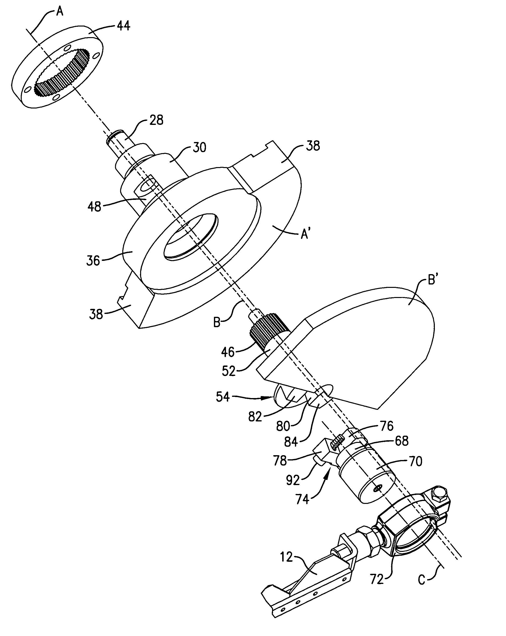
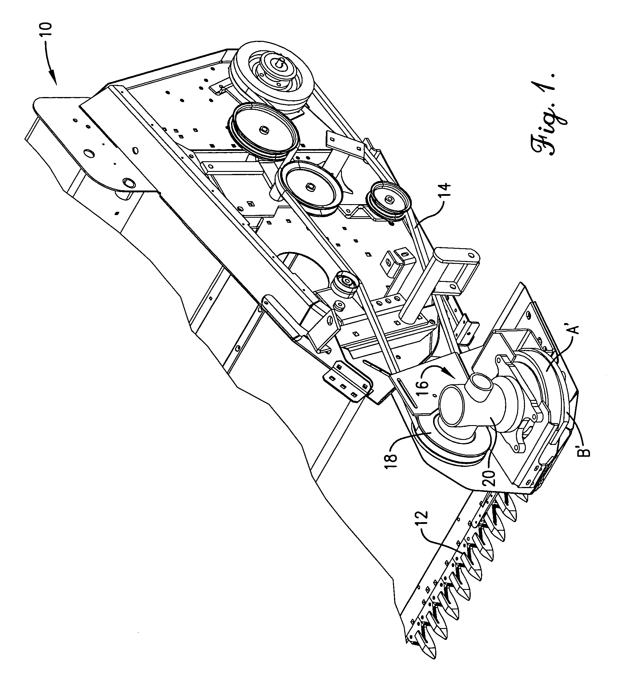
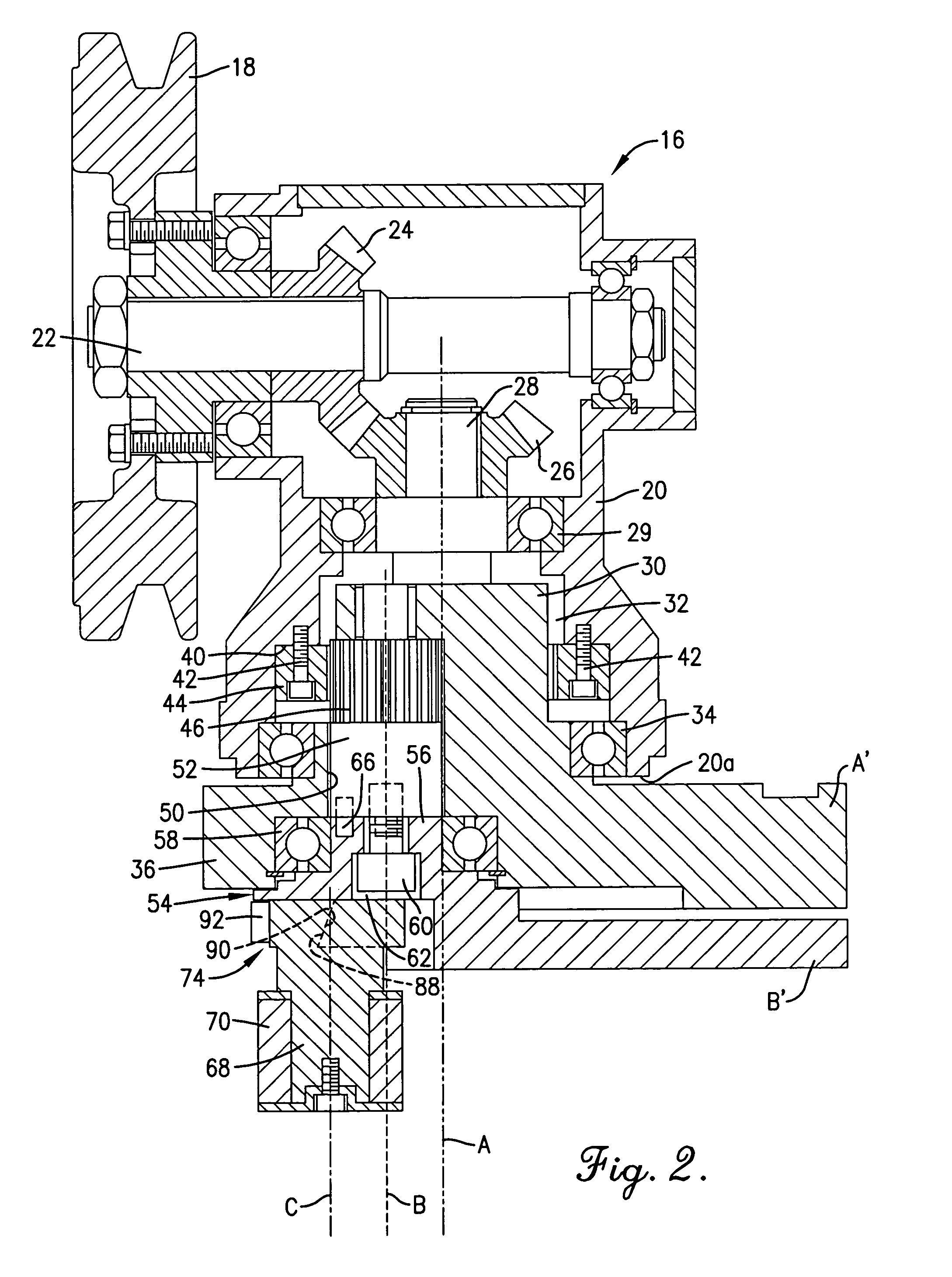
[0016]Referring initially to FIG. 1, a harvester has a header 10 having a sickle 12 at its lower front extremity for severing standing crops from the field as the harvester moves therethrough. At the left end of header 10 (as viewed from the rear of the machine looking forwardly), a belt drive assembly 14 receives driving power from a source (not shown) such as the mechanical driveline of a towing vehicle or the power output shaft of a self-propelled tractor on which the header 10 is mounted. Belt drive assembly 14 supplies input power to an epicyclic drive 16 coupled with sickle 12 for reciprocating the same across th...


PUM


Abstract

A counterbalancing epicyclic sickle drive has a pair of oppositely rotating weights that offset the inertial forces of the sickle during its abrupt acceleration and deceleration at opposite ends of its path of travel. One of the weights rotates with the main shaft of the drive about its longitudinal axis, while the second weight is fixed to an oppositely rotating crankshaft that orbits about the axis of the main shaft in eccentric relationship thereto. The weight on the main shaft is heavier than the weight on the crankshaft so as to offset changes in inertial forces produced by the crankshaft weight during increased acceleration of its center of gravity at opposite ends of its elliptical path of travel about the axis of the main shaft.

Description

TECHNICAL FIELD[0001]The present invention relates to harvesting equipment and, more particularly, to a smooth-running, counterbalancing drive for the reciprocating sickle of such a harvester.BACKGROUND AND SUMMARY[0002]Counterbalancing sickle drives are known in the art. See for example U.S. Pat. No. 3,941,003 owned by the assignee of the present invention. In that patent, a pair of equal counterbalance weights rotate in opposite directions about the axis of the main shaft of a gearbox that supplies driving power to the sickle. Each time the sickle approaches one end of its path of travel, the counter-rotating weights come into superimposed relationship with one another at the opposite end of the path of travel so as to counteract the inertia of the sickle. While this arrangement does a good job of counterbalancing the reciprocating sickle, it fails to compensate for the centrifugal force generated by an oscillating sway bar used in the translation of rotary motion from the gearbox...

Claims


Application Information

Patent Timeline
IPC IPC(8): A01D34/13
CPCA01D34/305Y10T74/18208A01D34/00A01D34/02A01D34/13
Inventor REGIER, BERNARD D.FUNK, JEFFREY S.
Owner AGCO CORP
Why Eureka
Eureka Blog
Learn More