Loading device

a technology of a loading device and a spherical tube, which is applied in the direction of liquid bottling, packaging goods type, special packaging, etc., can solve the problems of insufficient filling of the respective tube, large device size and bulk, and the need for expensive positioning to arrange the holes, etc., to achieve easy production, cost-effective effect, and easy to remov

Inactive Publication Date: 2006-10-17
BUCHEN ICS
View PDF7 Cites 11 Cited by
  • Summary
  • Abstract
  • Description
  • Claims
  • Application Information

AI Technical Summary

Benefits of technology

[0014]The invention generally provides a loading device and a procedure for loading a reactor made of a plurality of tubes, which allow the reactor resp. the tubes to be loaded as quickly and as simply as possible. The filling device should be as cost-effective and easy to produce as possible. It is also essential that the loading device is designed in such a way that incorrect use for example by an untrained operator is almost impossible or at least minimized. It is also essential that the loading device is suitable for gas-tight sealed reactors. The loading device should be stable, loadable and easy to remove. The tubes should be loaded as evenly as possible.

Problems solved by technology

This, in turn, causes an insufficient filling of the respective tube.
However, this is unacceptable due to the long filling time required.
The device is relatively large and bulky which is especially disadvantageous when the reactor is of a gas-tight type.
Further, expensive positioning is required to arrange the holes exactly above the filling openings.
The above mentioned devices substantially operate advantageously; however, they have the disadvantage that equal loading of all tubes is not always guaranteed.
The efficiency of the reactor becomes correspondingly lower and in extreme situations there can be risk of explosion if the input product in an insufficiently loaded tube is not totally transposed.
A further disadvantage of the described central devices, which provide rain-like distribution, is that a proportion of the bulk material does not fall directly into the tubes resp. filling openings, but also lands between the filling openings.
Without such a gap, dust can also get into the tubes and increase the quantity of catalyst material within the tubes.
Nevertheless, both types of segments have a common disadvantage, i.e. that the reactor has to be loaded manually by a person.
Besides this, loading also takes relatively long because, after filling, rests of the bulk material that was left on the segments have to be filled resp. swept into the filling openings.
Bridging can also not be precluded for sure.

Method used


Image

  • Loading device
  • Loading device
  • Loading device

Examples


Embodiment Construction

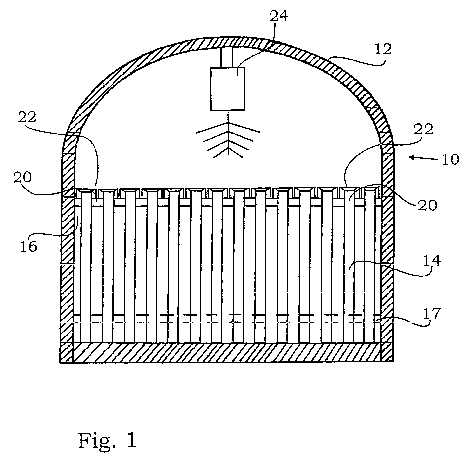
[0056]FIG. 1 explains the functional mode of a loading device 10 according to the invention within a reactor 12 with tubes 14. In the present example, the latter are held by a retaining base 16, through which the tubes 14 extend. Also shown is a lower retaining base 17, through which the tubes 16 also extend. Funnel elements 22 are arranged on tube ends 20 of the tubes 14. In plan view (not visible in FIG. 1), these form a closed surface. Above the funnel elements 22 is shown a pouring device 24, from which the bulk material falls rain-like on to the funnel elements 22. The rain-like distribution of the bulk material is indicated by the arrows. At this point it is emphasized that FIG. 1 is only a bloc diagram. The reactor 12, the tubes 14, the funnel elements 22 and the pouring device 24 only are symbolic representations.

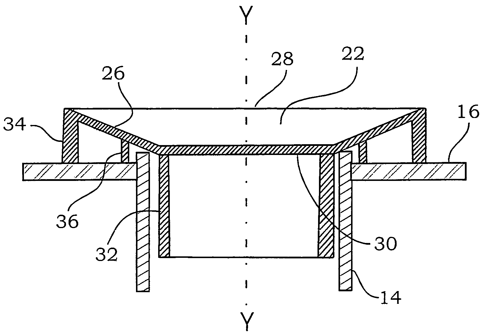
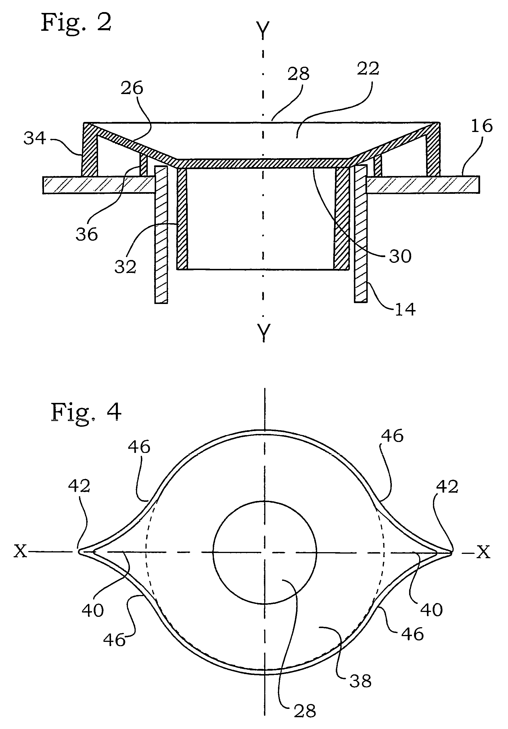
[0057]FIG. 2 shows a sectional view of a funnel element according to the invention. This has a funnel wall 26, which is limited by a filling opening 28, which are t...


PUM

PropertyMeasurementUnit
outer diameteraaaaaaaaaa
inner diameteraaaaaaaaaa
diameteraaaaaaaaaa

Abstract

The invention relates to a loading device for a reactor formed by of a plurality of tubes, which are substantially arranged vertically, substantially run parallel to each other and each have a filling opening. The loading device includes a plurality of funnel elements, through which the tubes can be loaded with bulk material, whereby the funnel elements are adapted to the reactor so that a substantially closed surface can be created with a plurality of funnel elements arranged side by side when the filling tubes extend into the tubes of the reactor through the filling openings. Furthermore, a pouring device for loading the tubes through the funnel elements is provided, whereby the pouring device is arranged above the funnel elements and lets the bulk material fall evenly rain-like onto all funnel elements.

Description

TECHNICAL FIELD OF INVENTION[0001]The present invention relates to a loading device for a reactor made up of a plurality of tubes, which are arranged in a substantially vertical direction, extend substantially parallel to one another, each comprising a filling opening.BRIEF DESCRIPTION OF RELATED ART[0002]Such reactors are, for example, used as catalysts in catalytic processes occurring in the petrochemical industry. They consist of a plurality of vertically arranged tubes, which are held together by one or several support plates to form a tube bundle or pack. These tubes are filled with a catalytically active material, mostly in the form of powder or granules through filling openings which are formed by open ends of the tubes. During operation, the tube bundle is closed gas-tight inter alia by a bell followed by leading the respective reaction gas into the bell and then through the filling openings through the tubes. The contents of the tubes, i.e. for example the granules, then en...

Claims


Application Information

Patent Timeline
Patent Type & Authority Patents(United States)
IPC IPC(8): B65B1/04
CPCB01J8/002B01J8/008B01J8/06B65G69/0458B01J2208/00752B01J2208/00769
Inventor GOEMANS, PIETTRAMPER, NICO
Owner BUCHEN ICS
Why Eureka
Try Eureka