Disc package

a technology for discs and packages, applied in the field of disc packages, can solve the problems of disc packaging costs increasing, discs may be separated, and troublesome screwing operation, and achieve the effect of deforming the cover

Inactive Publication Date: 2006-10-17
TAIYO YUDEN KK
View PDF13 Cites 25 Cited by
  • Summary
  • Abstract
  • Description
  • Claims
  • Application Information

AI Technical Summary

Benefits of technology

[0065]Therefore, in the disc package, the top end portion of the shaft can be moved to the position of the concave portion by effectively deforming the cover, in comparison with a case where the cover is not made of a flexible material.

Problems solved by technology

In the disc package described above, a troublesome screwing operation is required in order to fix the cover on the base.
Accordingly, the costs for the disc packaging are increased.
However, since a locking structure for locking the cover onto the base is not provided, the cover mounted on the base may be separated therefrom due to vibrations while the disc package is being transported.
However, the disc package has a disadvantage in that the cover cannot be fastened to the base simply by being pressurized onto the base.
Further, the cover cannot be mounted on the base unless it is precisely aligned along the circumference of the base.
If the cover is rotated in a reverse direction, it becomes impossible to separate the cover from the base.
Therefore, Japanese Utility Model Laid-Open Publication No. 4-84189 does not provide a disc package capable of allowing a cover to be fixed on a base simply by pressurizing the cover along a shaft axial direction with a locking mechanism for securely fixing the cover on the base.
Therefore, a user cannot recognize whether or not the cover can be separated from the base along the shaft axial direction.
Further, in this case, the cover cannot be separated from the base in a conventional way.
However, since they cannot be separated from each other even while being transported, transportation costs become increased.
However, in case the shaft is installed on the base by using the two methods described above, assembly equipments are required and further, more time should be spent in assembly.
As a result, an assembly cost becomes increased.
As a result, since the shaft is shaken on the base, it is hard for the shaft to be vertically maintained against the top surface of the base.
However, it is troublesome for a user to align the grooves with the protrusions.
In this case, however, if the cover is pressurized at a slight inclination angle onto the base, the end portion of the shaft and the concave portion of the cover may be misaligned.
As a result, a user cannot pressurize the cover anymore, so that the end portion of the shaft and the concave portion cannot be coupled.
Therefore, the cover cannot be mounted on the base.

Method used


Image

  • Disc package
  • Disc package
  • Disc package

Examples


first embodiment

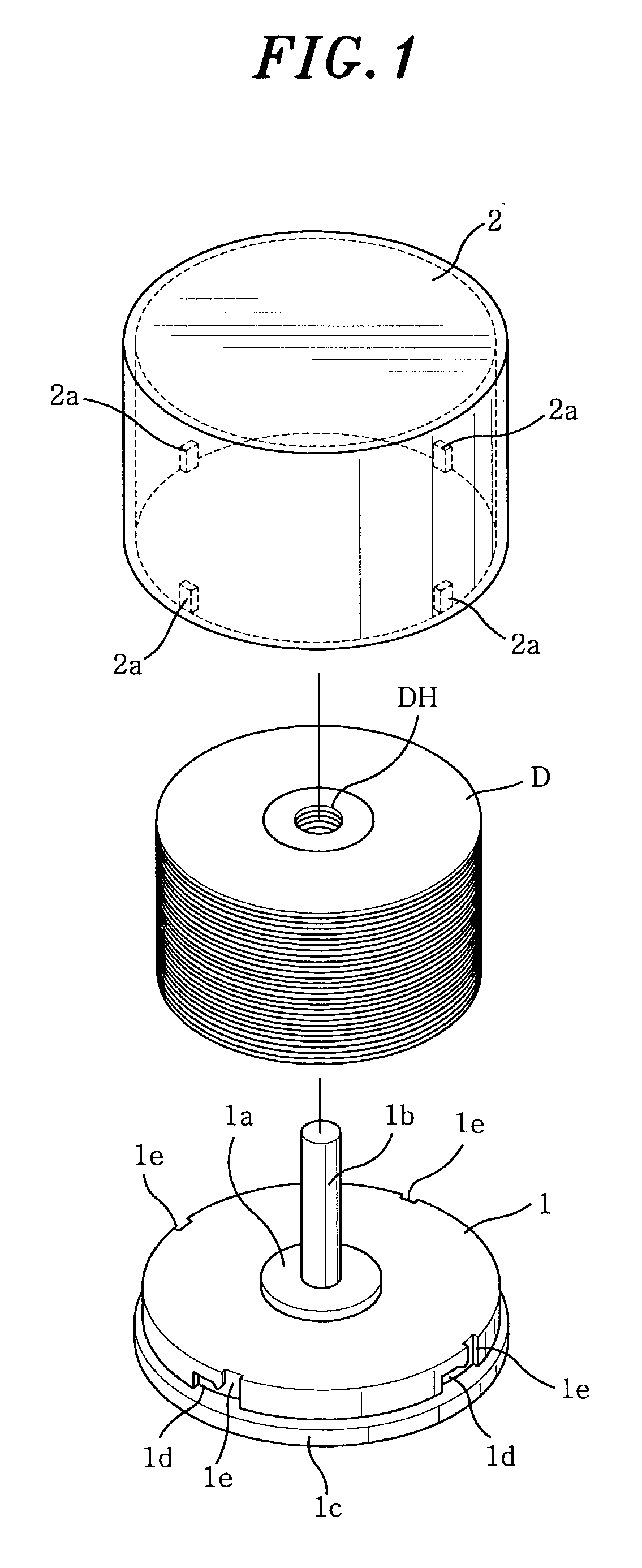
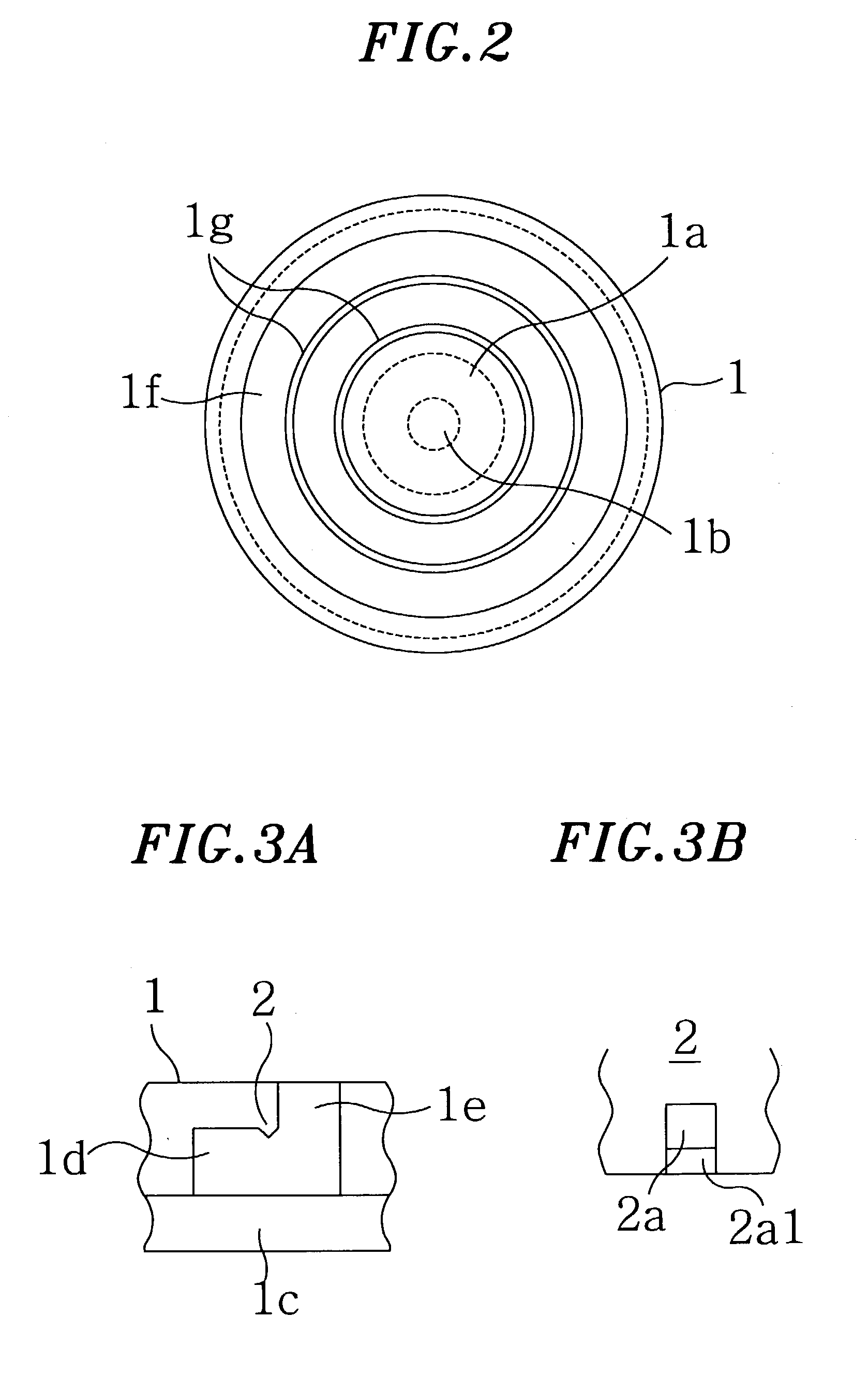
[0120]Though the protruded portions 2a are of the rectangular shape in the first preferred embodiment of the present invention, they can have a hemispheric shape as shown in FIGS. 6A and 6B, which have a similar effect to the rectangular protruded portions 2a. Further, though four protruded portions and four pull-out grooves are prepared in the first preferred embodiment, the base 1 and the cover 2 can be connected to or separated from each other by using the same simple mechanism as described in the first embodiment if the disc package has at least two protruded portions and two pull-out grooves.

second embodiment

[0121]FIG. 7 depicts a perspective view of a disc package in accordance with the present invention; FIG. 8, a bottom view of a base 11 shown in FIG. 7; FIG. 9A, an enlarged view of a protruded portion 11e of the base 11 shown in FIG. 7; FIG. 9B, an enlarged view of a coupling and a pull-out groove portion 12b and 12c of a bucket-shaped cover 12 shown in FIG. 7; FIGS. 10A and 10B, the way how the protruded portion 11e of the base 11 is fitted into and removed from the coupling groove portion 12b of the bucket-shaped cover 12 in the disc package shown in FIG. 7; and FIGS. 11A to 11C, a snap-fit locking mechanism of the disc package shown in FIG. 7.

[0122]As shown in FIG. 7, the disc package in accordance with the second embodiment of the present invention includes a base 11 and a cover 12. The base 11 has a disc shape. A circular protruded portion 11a is formed at the center of a top surface of the base 11. Installed at the center of the circular protruded portion 11a is a cylindrical ...

third embodiment

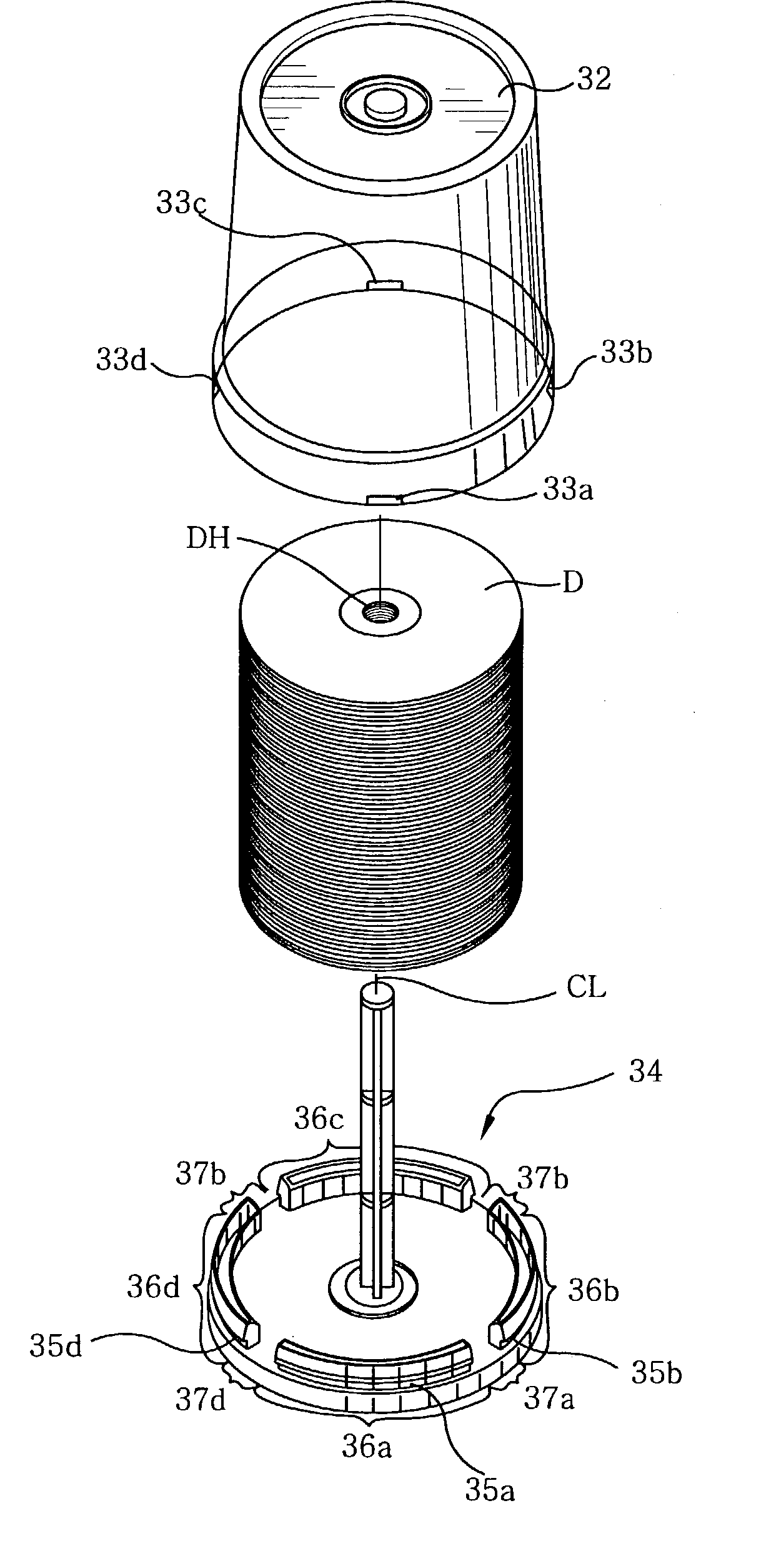
[0132]FIG. 13 shows a perspective view of a disc package in accordance with the present invention; FIG. 14, a bottom view of a base 21 shown in FIG. 13; FIG. 15A, an enlarged view of a coupling and a pull-out groove portion 21e and 21d of the base 21 shown in FIG. 13; FIG. 15B, an enlarged view of a protruded portion 22c of a bucket-shaped cover 22 shown in FIG. 13; FIGS. 16A and 16B, the way how the protruded portion 22c of the bucket-shaped cover 22 is fitted into and removed from the coupling groove portion 21e of the base 21 in the disc package shown in FIG. 13; and FIGS. 17A to 17C, a snap-fit locking mechanism of the disc package shown in FIG. 13.

[0133]As shown in FIG. 13, the disc package in accordance with the third preferred embodiment of the present invention includes a base 21 and a cover 22. The base 21 has a disc shape. A circular protruded portion 21a is formed at the center of a top surface of the base 21. Installed at the center of the circular protruded portion 21a ...


PUM

PropertyMeasurementUnit
timeaaaaaaaaaa
timeaaaaaaaaaa
circumferenceaaaaaaaaaa

Abstract

The present invention relates to a disc package having a structure in which a cover can be fixed on a base by simply pressurizing the cover with respect to the base in a base shaft axial direction and, at the same time, the cover can be prevented from being accidentally separated from the base while the disc package is being transported. Further, in the disc package, a cover once fixed on a base can be separated therefrom by rotating the cover along the circumference of the base in any direction, i.e., in either a clockwise or a counterclockwise direction. Furthermore, an end portion of a shaft can be fitted into a concave portion of a cover even in case the end portion of the shaft is not aligned with the concave portion of the cover.

Description

FIELD OF THE INVENTION[0001]The present invention relates to a disc package; and, more particularly, to a disc package for storing therein various types of discs, e.g., a read-only disc such as a CD and a DVD, a recordable disc such as a CD-R and a DVD-R, a rewritable disc such as a CD-RW and a DVD-RW, and the like.BACKGROUND OF THE INVENTION[0002]A conventional disc package capable of storing therein a plurality of discs includes a base on which the plurality of discs are stacked, a bucket-shaped cover for covering the discs mounted on the base, and a male screw cap for fixing the cover on the base.[0003]Installed at the center of a top surface of the base is a shaft to be inserted through a center hole of each disc. Formed on an upper end portion of the shaft is a female screw hole corresponding to the screw of the cap. The cover has a screw-through hole formed on a center portion of the upper surface thereof.[0004]A disc packaging process using the above-described disc package is...

Claims


Application Information

Patent Timeline
Patent Type & Authority Patents(United States)
IPC IPC(8): B65D85/57B65D85/02G11B33/04
CPCG11B33/045
Inventor ITO, TATSUICHIMORITA, KAZUHITOOYAMA, MASAKIMIYASHITA, TAKAYOSHISAITO, YOSHINORI
Owner TAIYO YUDEN KK
Why Eureka
Try Eureka