Spacer layer for electrophoretic display device

a display device and spacer layer technology, applied in the field of spacer layers of electrophoretic display devices, to achieve the effect of adequate resolution

Active Publication Date: 2006-10-17
E INK CORPORATION
View PDF10 Cites 39 Cited by
  • Summary
  • Abstract
  • Description
  • Claims
  • Application Information

AI Technical Summary

Benefits of technology

[0009]It is an object of the present invention to develop a structure for inclusion in the electrophoretic display device that permits formation of individual cells and adequate resolution.

Problems solved by technology

One of the major issues still needing to be addressed in the field of electrophoretic displays is resolution of the images displayed.

Method used


Image

  • Spacer layer for electrophoretic display device
  • Spacer layer for electrophoretic display device
  • Spacer layer for electrophoretic display device

Examples


Embodiment Construction

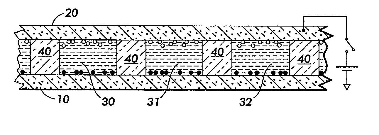
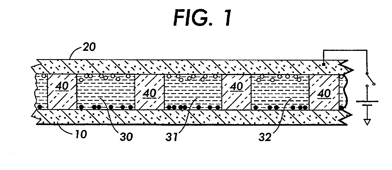
[0026]As illustrated in FIG. 1, the electrophoretic display device of the invention comprises two conductive film substrates 10 and 20 disposed oppositely of each other. Between the conductive film substrates are contained a multiplicity of individual reservoirs (30, 31, 32), each filled with a display liquid described more fully below. Each of the individual reservoirs defines one cell of the electrophoretic display device. The individual reservoirs are kept separate from one another by a spacer 40.

[0027]The display device may have any suitable overall length and width as desired. Preferably, the spacer layer comprises a single, unitary layer within the device, and thus the spacer layer is manufactured to have a length and width corresponding to that of the overall device. The electrophoretic display device may also be made to have any desired height, although a total height of from about 20 to about 400 microns is preferred in terms of size and ease of use of the device.

[0028]The ...


PUM

PropertyMeasurementUnit
widthaaaaaaaaaa
thicknessesaaaaaaaaaa
heightaaaaaaaaaa

Abstract

An electrophoretic display device includes a spacer layer sandwiched between two conductive film substrates, the spacer layer defining a multiplicity of individual reservoirs within the display device which are filled with a display liquid. The spacer layer preferably is one of (a) a screen in which holes within the screen define the individual reservoirs, (b) a laser punched spacer layer comprised of a sheet having holes laser punched therein in which the laser punched holes define the individual reservoirs, (c) a pocket spacer layer comprised of sheets joined together and containing a pattern of pockets within the sheets in which the pockets define the individual reservoirs, (d) an etched photoresist layer formed upon one of the conductive film substrates in which holes etched in the photoresist layer define the individual reservoirs, and (e) a composite etched layer comprised of a composite of two photoresist layers sandwiching a conductive film in which holes etched in the composite define the individual reservoirs. The device can display both monochrome and color images.

Description

CROSS REFERENCE TO RELATED APPLICATIONS[0001]This Application is related to U.S. patent application Ser. No. 09 / 683,534 (now U.S. Pat. No. 6,574,034), Ser. No. 09 / 683,535 (now U.S. Pat. No. 6,529,313), Ser. No. 10 / 046,194 (now U.S. Pat. No. 6,577,433), and Ser. No. 10 / 046,510 (now U.S. Pat. No. 6,525,866), each filed on Jan. 16, 2002 and incorporated herein by reference in their entireties.BACKGROUND OF THE INVENTION[0002]1. Field of Invention[0003]This invention relates to spacer layers for an electrophoretic display device, and methods for making such spacer layer.[0004]2. Description of Related Art[0005]Electrophoretic displays, also more commonly referred to as electronic paper, are well known in the art. An electrophoretic display generally comprises a suspension of charged pigment particles colloidally dispersed in a liquid of matching specific gravity contained in a cell comprising two parallel and transparent conducting electrode panels. The charged particles are transported...

Claims


Application Information

Patent Timeline
Patent Type & Authority Patents(United States)
IPC IPC(8): G09G3/34G02B26/00G02F1/1333G02F1/167
CPCG02F1/167G02F1/133377
Inventor LIN, PINYENPAN, DAVID H.CHENG, CHIEH-MINHOLDEN, DAVID E.BUSH, ADAM
Owner E INK CORPORATION
Why Eureka
Try Eureka