
Methods and systems for inspecting reticles using aerial imaging and die-to-database detection

Active Publication Date: 2006-10-17
KLA TENCOR CORP
View PDF73 Cites 136 Cited by
  • Summary
  • Abstract
  • Description
  • Claims
  • Application Information

AI Technical Summary

Benefits of technology

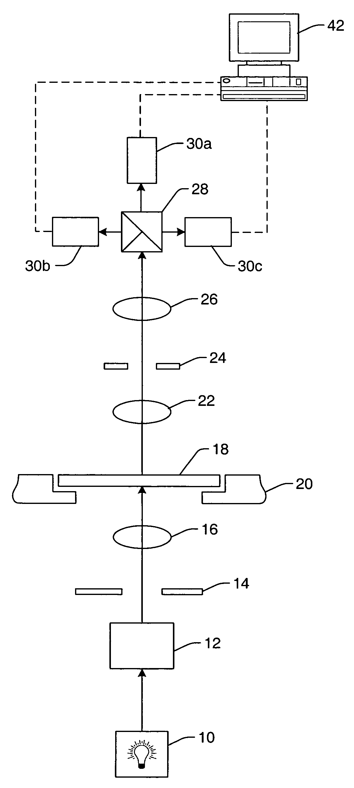
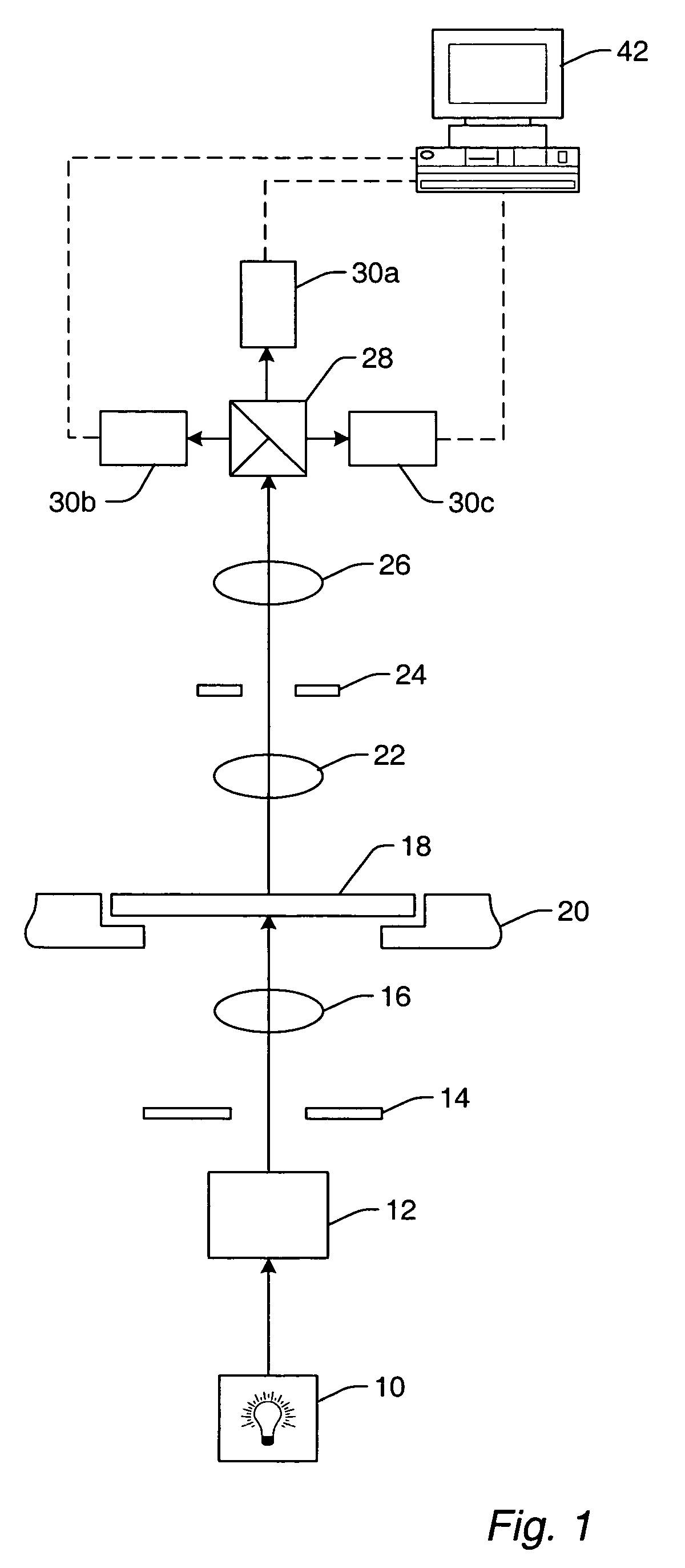
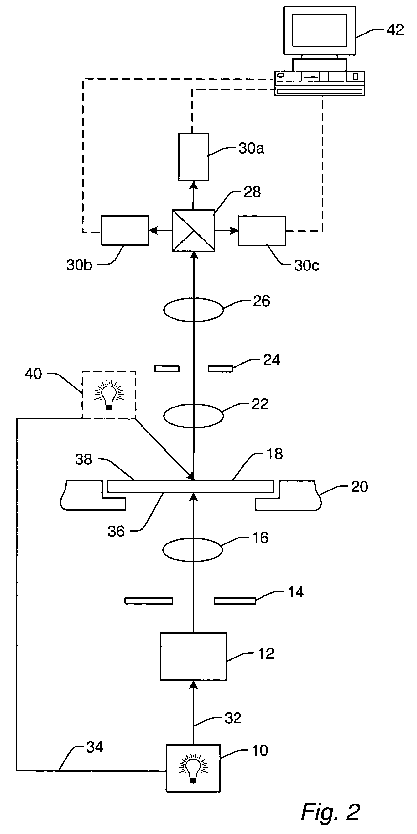
[0023]The image computer may also be configured to perform one or more functions on the image data. For example, the one or more functions may include detecting defects on the reticle by comparing a first portion of the image data from the inspection subsystem to a second portion of the image data from the inspection subsystem. In an embodiment, the one or more functions may include detecting defects on the reticle by comparing image data from the inspection subsystem to a reference image of the reticle stored in a database. The image computer may be further configured to generate a database that includes a reference image of the reticle. In an additional embodiment, the one or more functions may include detecting defects on the reticle using the image data from the inspection subsystem and classifying defects using the image data from the inspection subsystem or the review subsystem. In a further embodiment, t

Problems solved by technology

Therefore, a substantial portion of the defects may include defects that would be printed onto the specimen by the exposure system using the reticle under the set of exposure conditions.
In this manner, the defects may be differences between the aerial image and an image that if printed onto a resist may produce a selected pattern in the resist.
As such, the detected defects may include defects in a patterned resist that may be caused by the reticle.

Method used


Image

  • Methods and systems for inspecting reticles using aerial imaging and die-to-database detection
  • Methods and systems for inspecting reticles using aerial imaging and die-to-database detection
  • Methods and systems for inspecting reticles using aerial imaging and die-to-database detection

Examples


Embodiment Construction

[0046]As used herein, the term “reticle” is used to refer to a reticle or a mask. The term reticle may also refer to different types of reticle including, but not limited to, a clear-field reticle, a dark-field reticle, a binary reticle, a phase-shift mask (PSM), an alternating PSM, an attenuated or halftone PSM, and a ternary attenuated PSM, which are described in more detail above. A reticle, as described herein, may or may not include a pellicle. The term reticle may also be used to refer to a reticle that includes optical proximity correction (OPC) features. OPC features are designed to reduce distortions of an image printed using the reticle by reducing optical proximity effects. The term “optical proximity effects” generally refers to variations in lateral dimensions of printed features due to the proximity of other features on the reticle. Such effects may be reduced by determining the distortions due to the optical proximity effects and altering the features on the reticle t...


PUM


Abstract

Methods and systems for inspecting a reticle are provided. In an embodiment, a method may include forming an aerial image of the reticle using a set of exposure conditions. The reticle may include optical proximity correction (OPC) features. The method may also include detecting defects on the reticle by comparing the aerial image to a reference image stored in a database. The reference image may be substantially optically equivalent to an image of the reticle that would be printed on a specimen by an exposure system under the set of exposure conditions. The reference image may not include images of the OPC features. Therefore, a substantial portion of the defects include defects that would be printed onto the specimen by the exposure system using the reticle under the set of exposure conditions. The method may also include indicating the defects that are detected in critical regions of the reticle.

Description

PRIORITY CLAIM[0001]This application claims priority to U.S. Provisional Application No. 60 / 418,887 entitled “Methods and Systems for Inspecting Reticles Using Aerial Imaging and Die-to-Database Detection,” filed Oct. 15, 2002.BACKGROUND OF THE INVENTION[0002]1. Field of the Invention[0003]This invention generally relates to systems and methods for reticle inspection. Certain embodiments relate to systems and methods for inspecting reticles using aerial imaging and die-to-database detection.[0004]2. Description of the Related Art[0005]Semiconductor fabrication processes typically involve a number of lithography steps to form various features and multiple levels of a semiconductor device. Lithography involves transferring a pattern to a resist formed on a semiconductor substrate, which may be commonly referred to as a wafer. A reticle or a mask may be disposed above the resist and may have substantially transparent regions and substantially opaque regions configured in a pattern that...

Claims


Application Information

Patent Timeline
IPC IPC(8): G01N21/00G03F1/00G06K9/03
CPCG01N21/95607G03F1/84G01N2021/95615G01N2021/95676
Inventor STOKOWSKI, STANALLES, DAVID
Owner KLA TENCOR CORP
Learn More