Communication station with automatic cable loss compensation

a communication station and automatic technology, applied in the field of wireless digital communication systems, can solve the problems of overpowering or underpowering the rf amplifier, significant amount of rf energy loss, and power loss through the cable varies,

Inactive Publication Date: 2006-10-17
INTERDIGITAL TECH CORP
View PDF13 Cites 69 Cited by
  • Summary
  • Abstract
  • Description
  • Claims
  • Application Information

AI Technical Summary

Benefits of technology

[0013]The present invention compensates for the variability of transmitted RF signal levels in a CDMA system where a cable connects ground-based low signal level RF equipment with remotely located RF power amplification equipment. The RF signal level is measured at the ground-based RF equipment end of the cable and also at the RF power amplifier equipment end of the cable. Changes in the loss across the cable are compensated with variable attenuators.

Problems solved by technology

A significant amount of RF energy is lost through the cable connecting the ground station to the antenna.
In addition, the power loss through the cable varies with temperature.
This variability causes a variation in signal level to the RF amplifier, which can result in overpowering or underpowering the RF amplifier.
Overpowering the RF amplifier can cause interference with neighboring cell sites and can cause distortion of the transmitted signal which produces additional undesirable noise.
Underpowering the RF amplifier can result in the transmission of a signal that is too weak to effectively communicate with the subscriber units within the cell area of the transmitter.
Since this measurement is typically made at the ground station, variability in power loss through the cable also adversely affects the accuracy of the received power measurement.

Method used


Image

  • Communication station with automatic cable loss compensation
  • Communication station with automatic cable loss compensation
  • Communication station with automatic cable loss compensation

Examples


Embodiment Construction

[0020]The preferred embodiments will be described with reference to the drawing figures where like numerals represent like elements throughout.

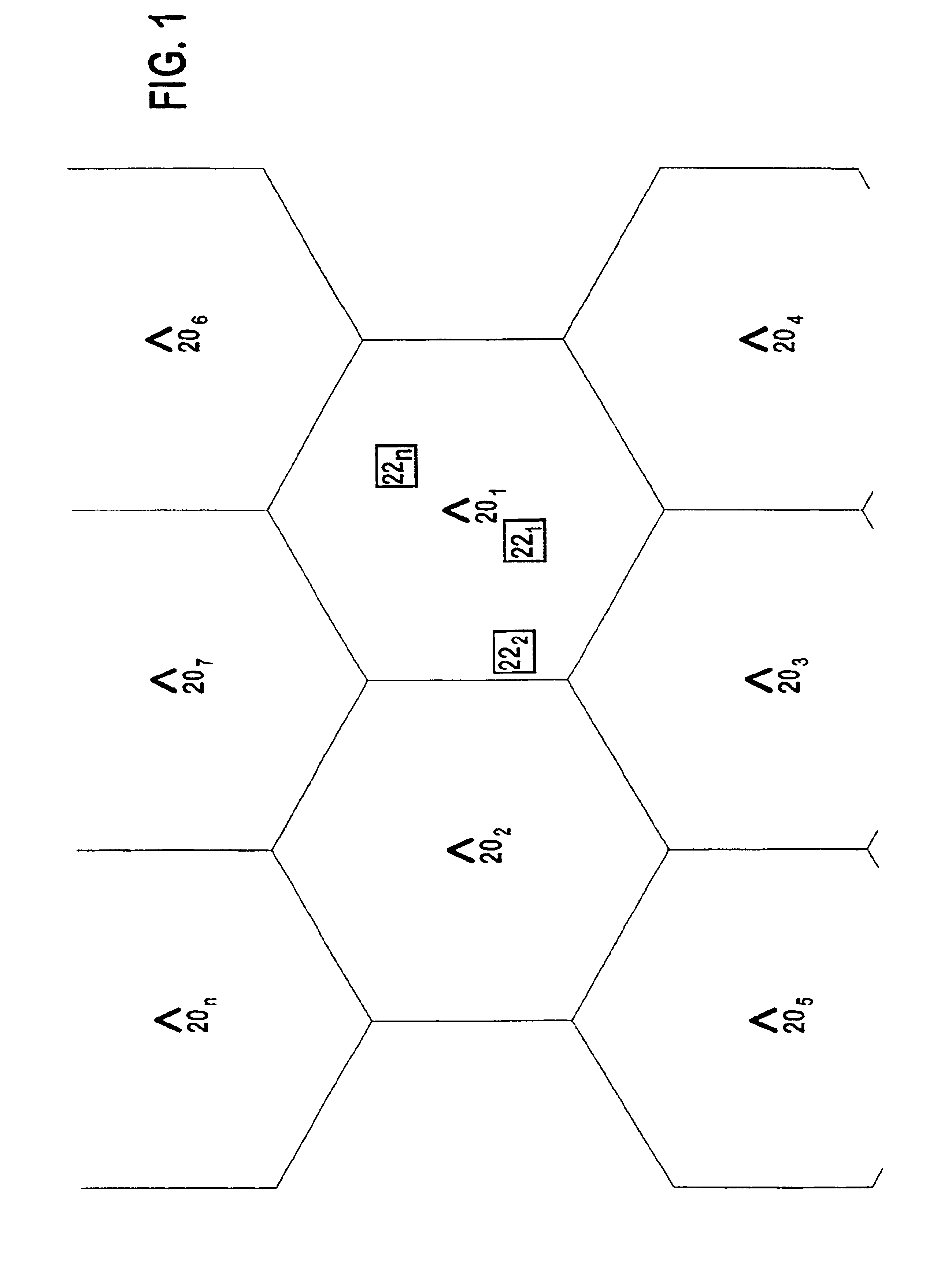
[0021]A communications network employing the present invention is shown in FIG. 1. The communications network includes a plurality of base stations 201, 202, . . . 20n, each of which supports wireless communication with mobile and fixed subscriber units 221, 222, . . . 22n that are located within the coverage area of the respective base station 201, 202, . . . 20n.

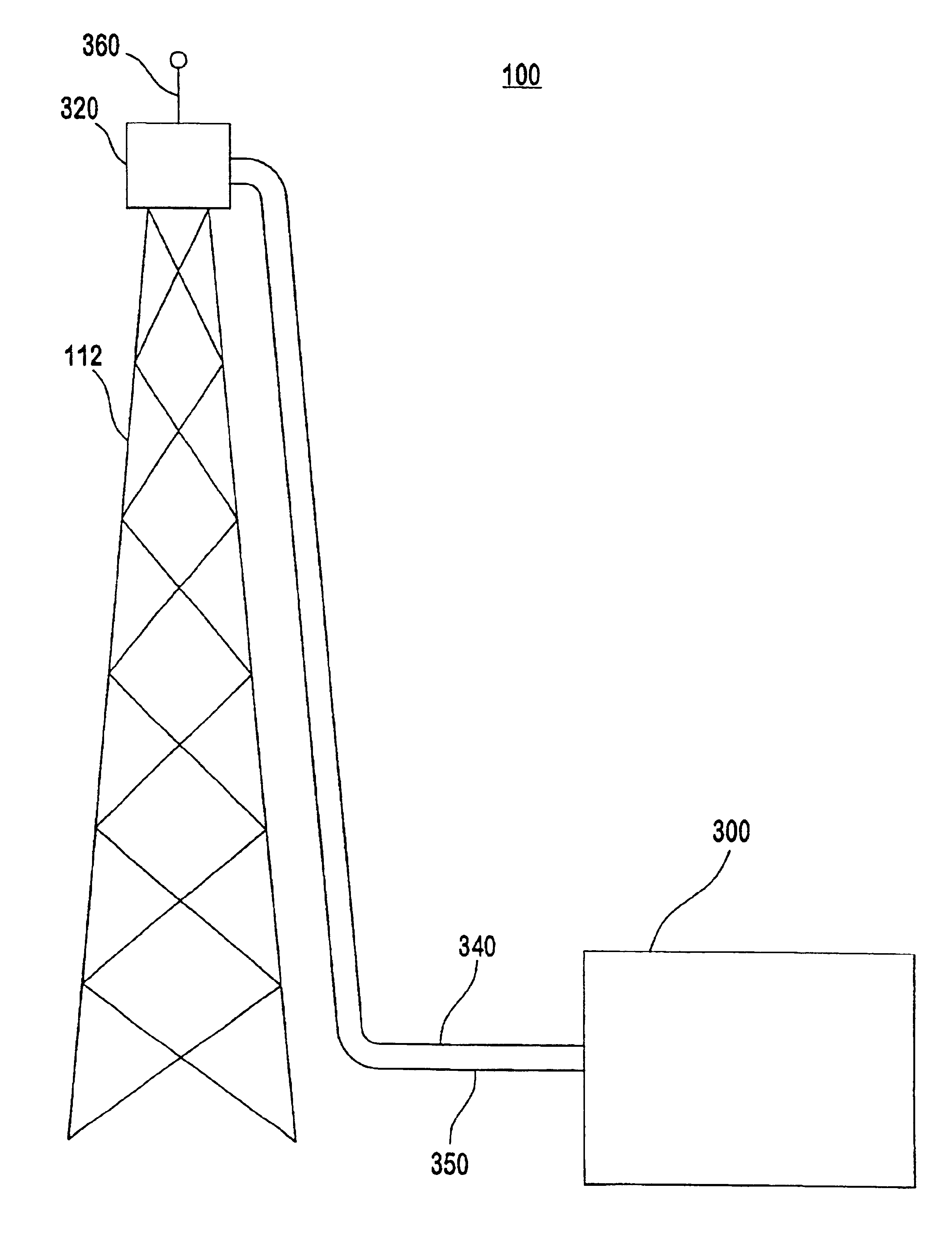
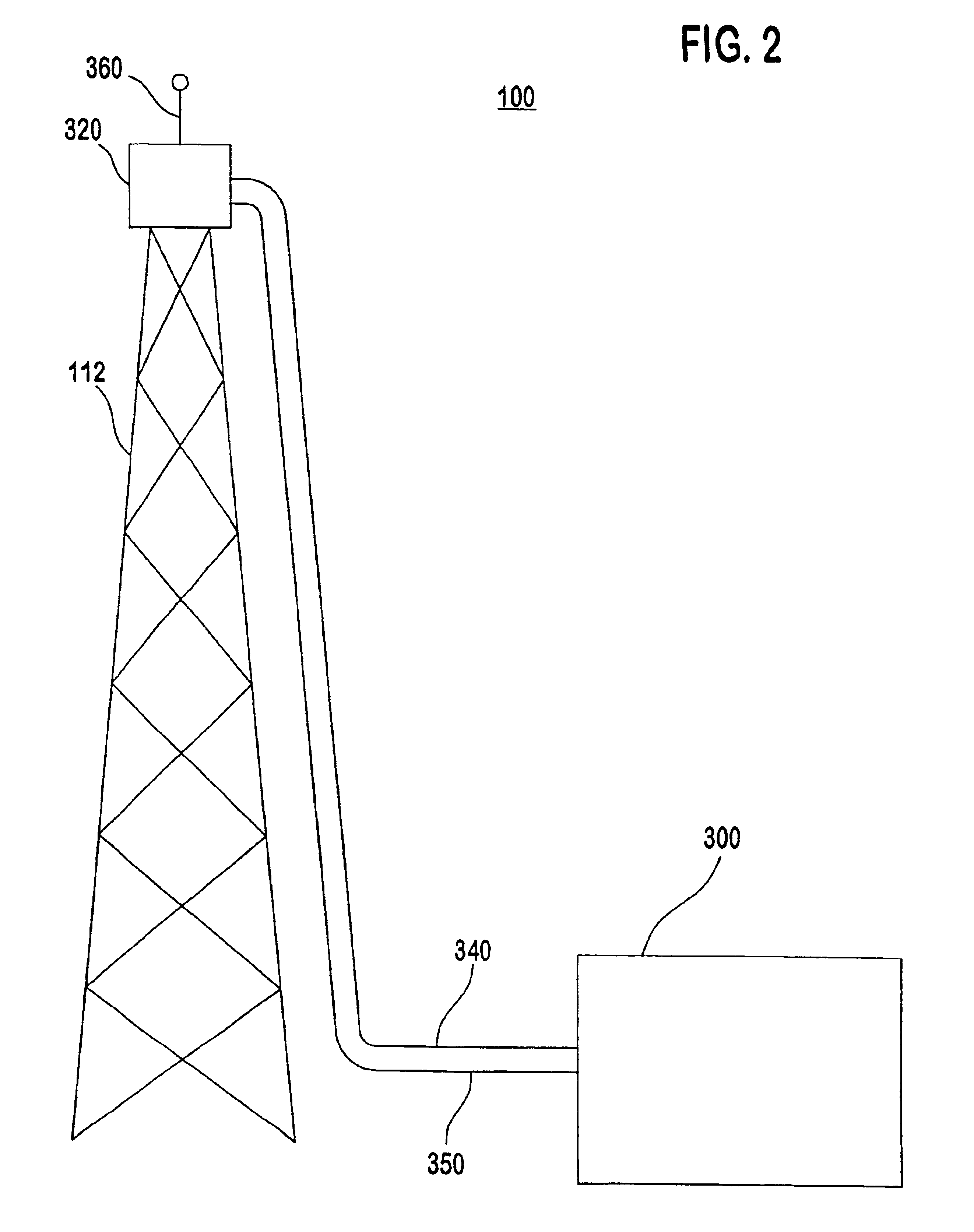
[0022]Referring to FIG. 2, a base station 100 with ground-based receiving and transmitting equipment 300, a remotely located mast head unit 320 and an antenna 360 mounted upon a tower 112 is shown. The mast head unit 320 includes an RF power amplifier and related electronics. A coaxial cable 340 conveys RF signals between the ground-based equipment 300 and the mast head unit 320. These signals include the incoming signals which are received from subscriber units 221, 222, . . . 22n ...


PUM


Abstract

A wireless communications systems employing code-division multiple access information transmission techniques includes a transmission facility having ground-based transmission and reception electronic equipment, a remotely located RF power amplifier, an antenna, and an RF cable connecting the ground-based equipment with the remotely located RF power amplifier. Power level detectors in the ground-based equipment and in the remotely located RF power amplifier measure the signal level at each end of the RF cable. A microcontroller compares these measurements and adjusts a variable attenuator in the transmission signal path and a variable attenuator in the received signal path to compensate for signal level variability due to variations in signal loss.

Description

[0001]This application is a 35 U.S.C. §371 national stage application of international application PCT / US99 / 30652, filed Dec. 23, 1999 which claims priority from U.S. provisional application No. 60 / 118,824, filed on Feb. 5, 1999.BACKGROUND OF THE INVENTION[0002]1. Field of the Invention[0003]The present invention relates to wireless digital communications systems. More particularly, the present invention relates to a code-division multiple access (CDMA) communication system employing a base station having remotely located RF power amplification equipment.[0004]2. Description of the Prior Art[0005]CDMA systems provide an efficient use of the limited bandwidth of the RF spectrum, thereby permitting a greater amount of information transmission with less signal distortion than communications systems using other techniques, such as time division multiple access and frequency division multiple access.[0006]In a CDMA communication system, an information signal at the transmitter is mixed w...

Claims


Application Information

Patent Timeline
Patent Type & Authority Patents(United States)
IPC IPC(8): H04M1/00
CPCH04W88/08
Inventor BIRD, JOHNKAZAKEVICH, LEONID
Owner INTERDIGITAL TECH CORP
Why Eureka
Try Eureka