
Press and method of manufacturing a can end

a technology of can end and press, which is applied in the field of apparatus and method for forming can end panels or can bodies, can solve the problems of can end and/or can end finishes in the can end

Active Publication Date: 2006-10-24
STOLLE MACHINERY
View PDF20 Cites 57 Cited by
  • Summary
  • Abstract
  • Description
  • Claims
  • Application Information

AI Technical Summary

Benefits of technology

[0009]Accordingly, an object of the present invention is to provide a method and apparatus for forming a can end or can body from material that substantially reduces wrinkling in the can end or can body.

Problems solved by technology

Wrinkles can cause problems in the finishes in the dome of the can body and / or can end, for example, by causing cracks in the epoxy placed on the can body and / or can end.

Method used


Image

  • Press and method of manufacturing a can end
  • Press and method of manufacturing a can end
  • Press and method of manufacturing a can end

Examples


Embodiment Construction

[0023]For purposes of the description hereinafter, the terms “upper”, “lower”, “vertical”, “horizontal”, “top”, “bottom”, “aft”, “behind”, and derivatives thereof shall relate to the invention, as it is oriented in the drawing FIGS. However, it is to be understood that the invention may assume various alternative configurations except where expressly specified to the contrary. It is also to be understood that the specific elements illustrated in the drawings and described in the following specification are simply exemplary embodiments of the invention. Therefore, specific dimensions, orientations and other physical characteristics related to the embodiments disclosed herein are not to be considered limiting.

[0024]As employed herein, the term “number” refers to one or more than one (i.e., a plurality). As employed herein, the term “fastener” refers to any suitable fastening, connecting or tightening mechanism expressly including, but not limited to, integral rivets. As employed herei...


PUM


Abstract

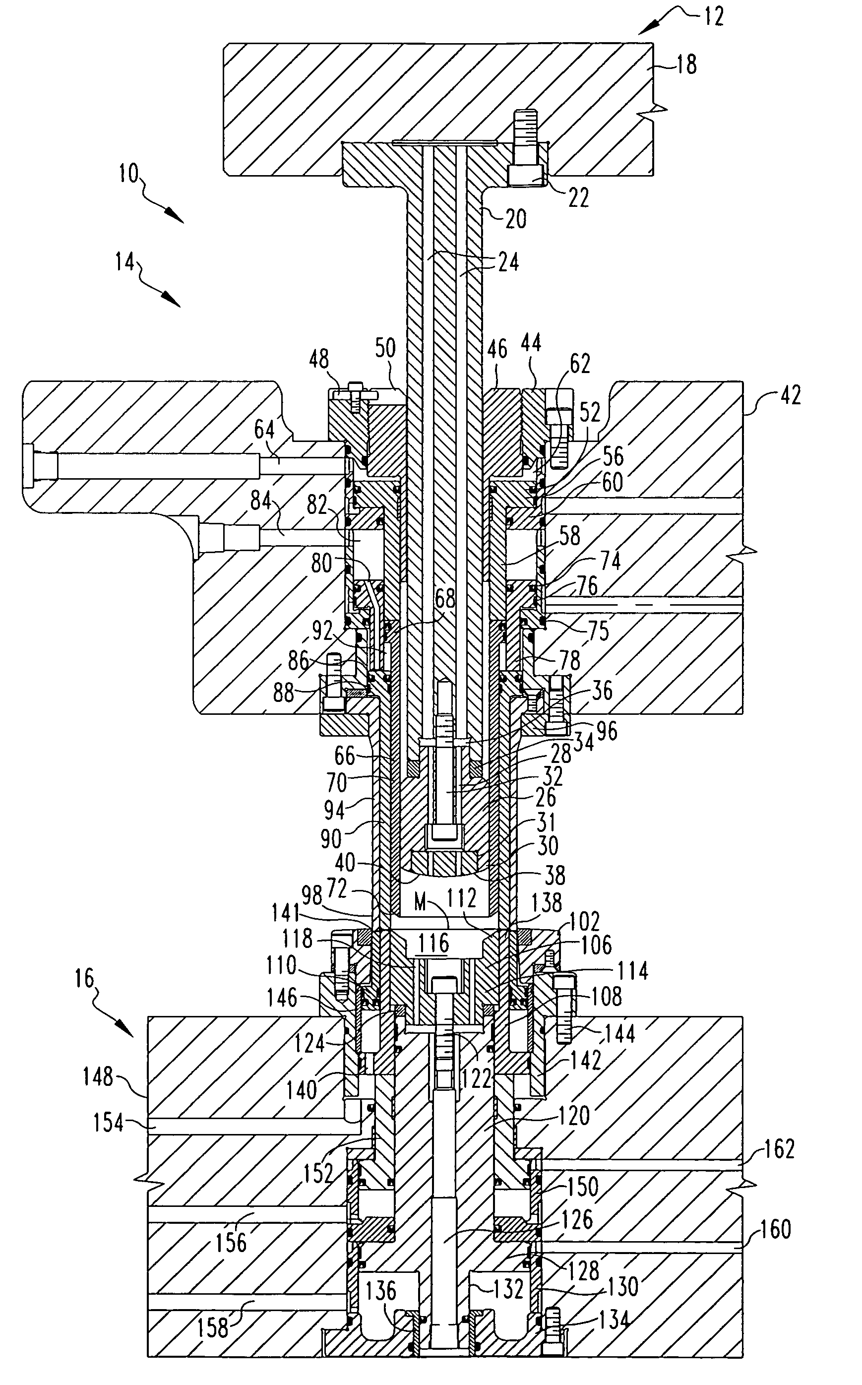
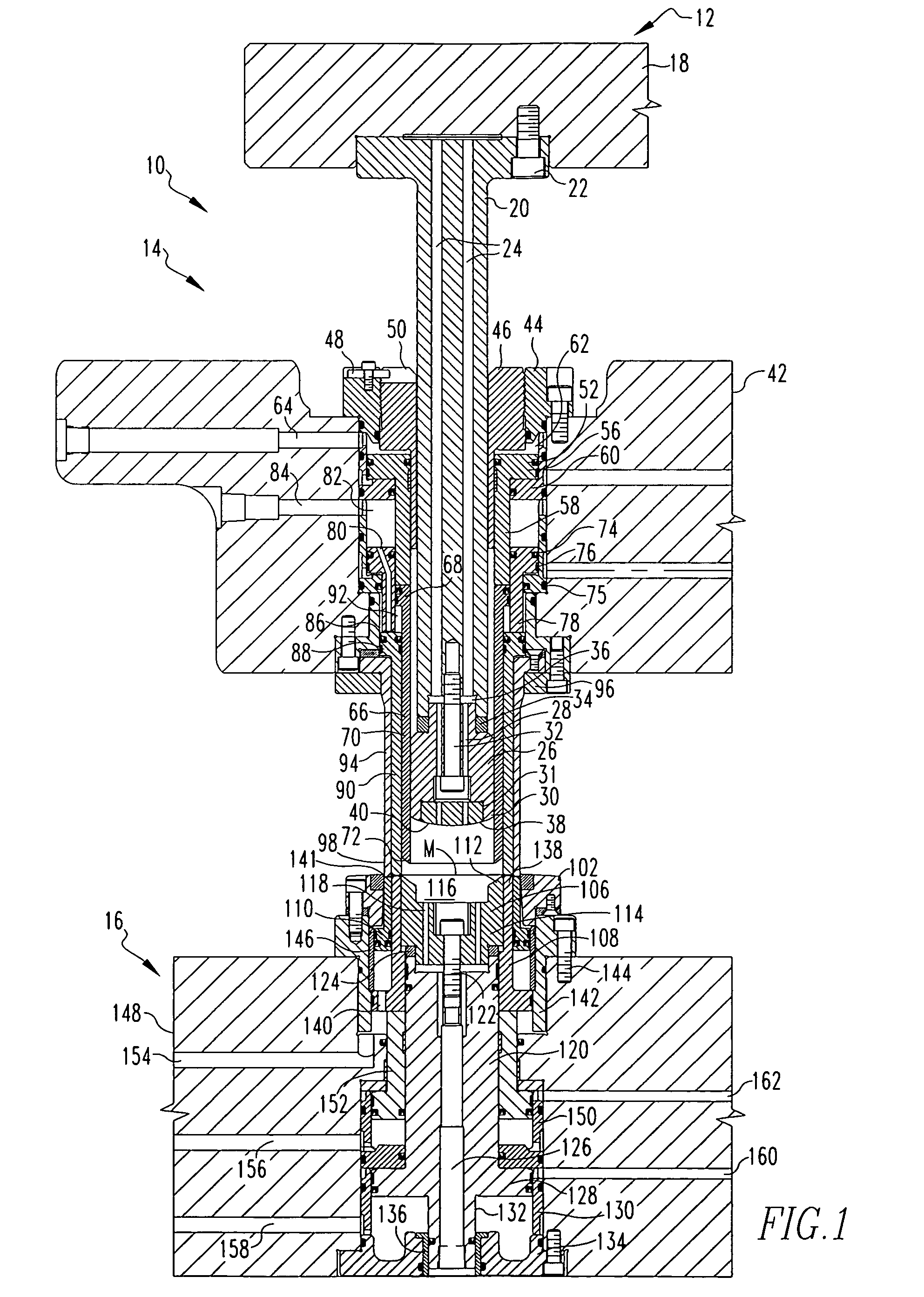
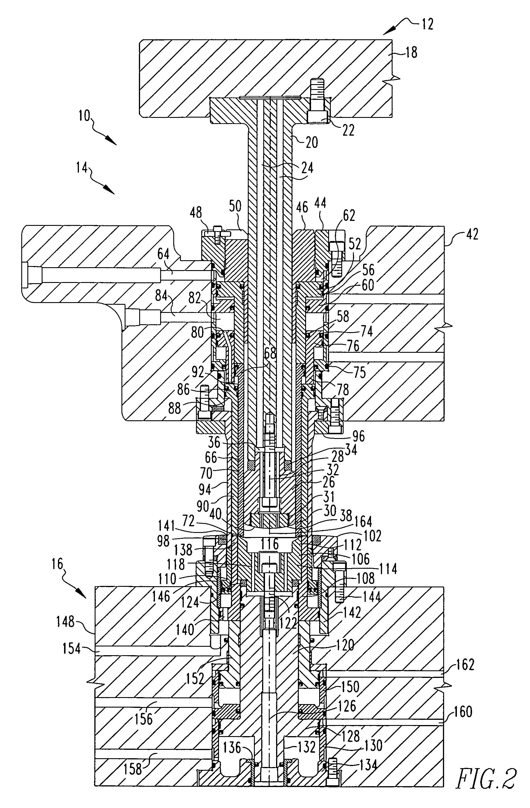
An apparatus and method for forming a can end having an annular ridge and a central panel and a can body with a can bottom is provided that exhibits reduced wrinkling in the material used to form the can end and can body. The method of the invention uses a two step doming process wherein material is first drawn or stretched and then held by a punch core ring and then further drawn, stretched or domed and then held by a punch core. The apparatus and method of the invention also include a lower piston located above an upper pressure sleeve and radially outward from a punch core ring wherein the lower piston has a bore and the lower piston, punch core ring and upper pressure sleeve define a gap to which pressurized gas may be supplied through the bore to selectively axially actuate the punch core ring.

Description

FIELD OF THE INVENTION[0001]The present invention generally relates to an apparatus and method for forming can bodies or container end panels, commonly called can ends, from a sheet of material. More particularly, the present invention relates to an apparatus and method for forming can bodies or container end panels, commonly used for the bottom of cans, wherein the can bodies or can ends exhibit reduced wrinkling.BACKGROUND OF THE INVENTION[0002]It is well known to draw and iron a sheet metal blank to make a thin walled can body for packaging carbonated beverages, non-carbonated beverages, food or other substances within the can body. In a conventional can body, a bottom profile of the can body includes an outwardly protruding annular ridge near the periphery of the can body, and a slope inwardly from the annular ridge that forms an inwardly projecting dome portion of the can body, called a domed can end.[0003]In a two-piece can, the dome would be formed directly into the bottom of...

Claims


Application Information

Patent Timeline
IPC IPC(8): B21D22/00
CPCB21D22/30B21D51/26
Inventor MCCLUNG, JAMES A.
Owner STOLLE MACHINERY
Learn More