Manual bulk liquid pump control and distribution system

a distribution system and bulk liquid technology, applied in the direction of piston pumps, positive displacement liquid engines, packaging goods types, etc., can solve the problems of daily spills on each and every delivery, no longer any tolerance for these types of frequent spills, and extreme cost of underground storage of tanks

Inactive Publication Date: 2006-10-24
SAFETY PUMPING SYST
View PDF6 Cites 8 Cited by
  • Summary
  • Abstract
  • Description
  • Claims
  • Application Information

AI Technical Summary

Benefits of technology

[0025]The principal object of the manual bulk liquid pump control and distribution system is to create a unique system that will eliminate substantially all spillage of liquids during the transfer from one containment vessel to a second containment vessel.
[0026]Another object of the manual bulk liquid pump control and distribution system is to create a unique way to move bulk liquids in two different directions through a single flow reversing two-way valve without reversing the direction of the pump drive unit.

Problems solved by technology

Accordingly, it is extremely expensive to put a tank underground.
There is no longer any tolerance for these types of frequent spills.
The fuel oil transportation industry and chemical transportation industry have problems that are similar to the petroleum industry.
This results in daily spills on each and every delivery, which is no longer an accepted practice.
This system does not have the capability of drawing excess liquid from the hose, or drawing a liquid out of a container back into the truck container.
This patent describes a method of forcing a liquid out of a container but has no way of drawing a liquid back into the container from the hose or from another container.
This is a sophisticated pump and control circuit, but does not offer the capabilities of the two-way valve system where a pump running at a constant speed can both control the volume and pump liquid in either direction from two containment vessels.
None of the foregoing prior art teaches or suggests the particular unique features of the manual bulk liquid pump control and distribution system.

Method used


Image

  • Manual bulk liquid pump control and distribution system
  • Manual bulk liquid pump control and distribution system
  • Manual bulk liquid pump control and distribution system

Examples


Embodiment Construction

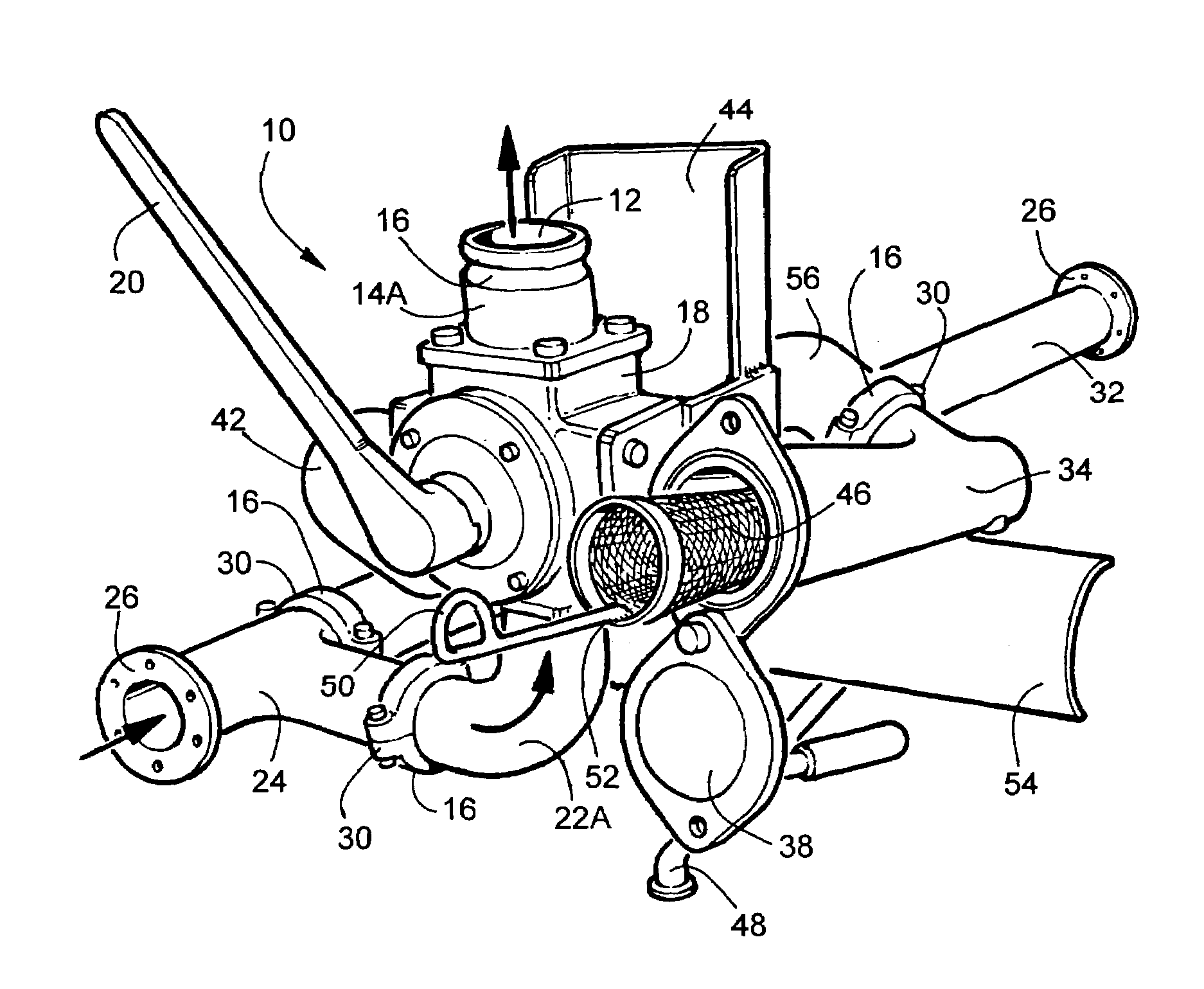
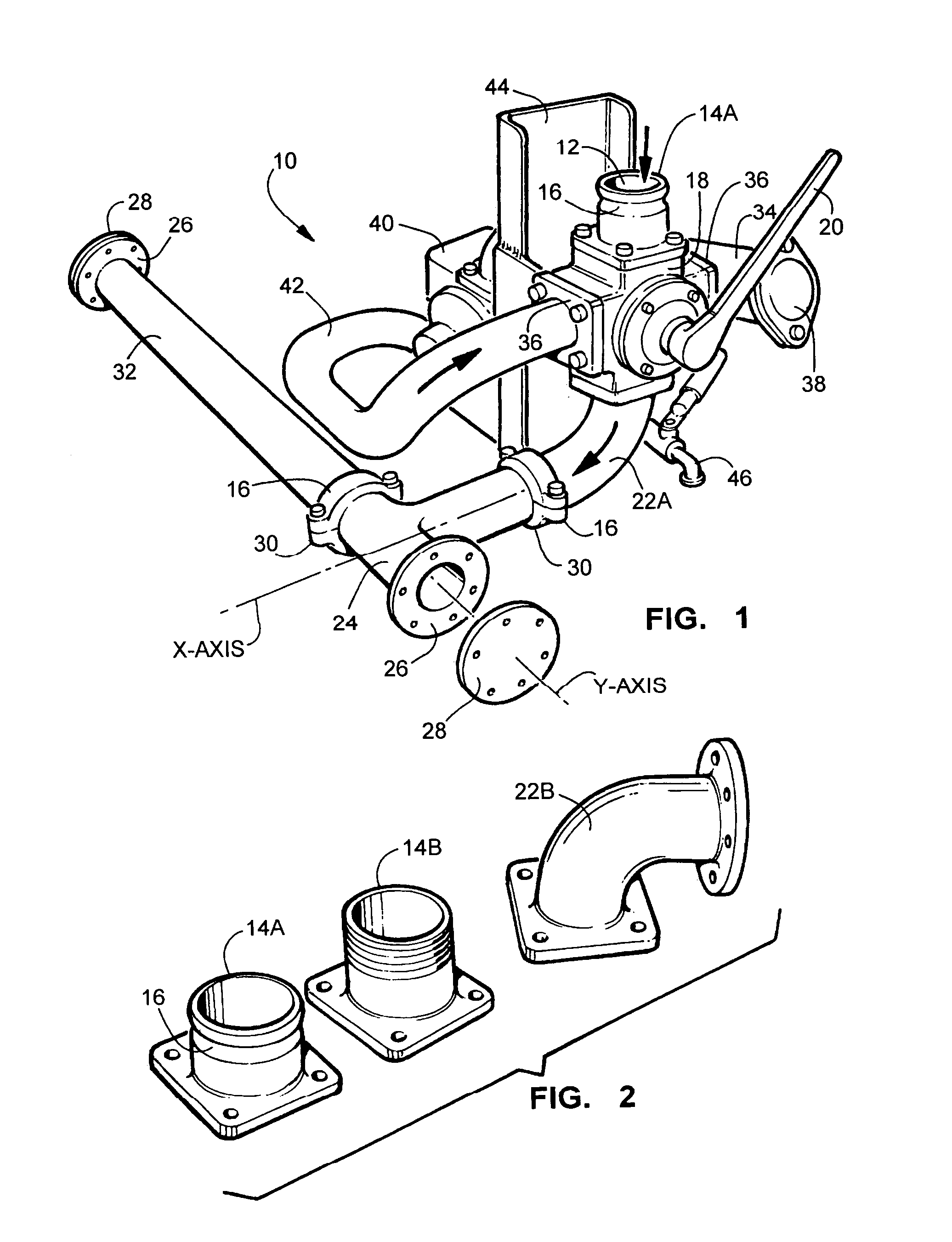
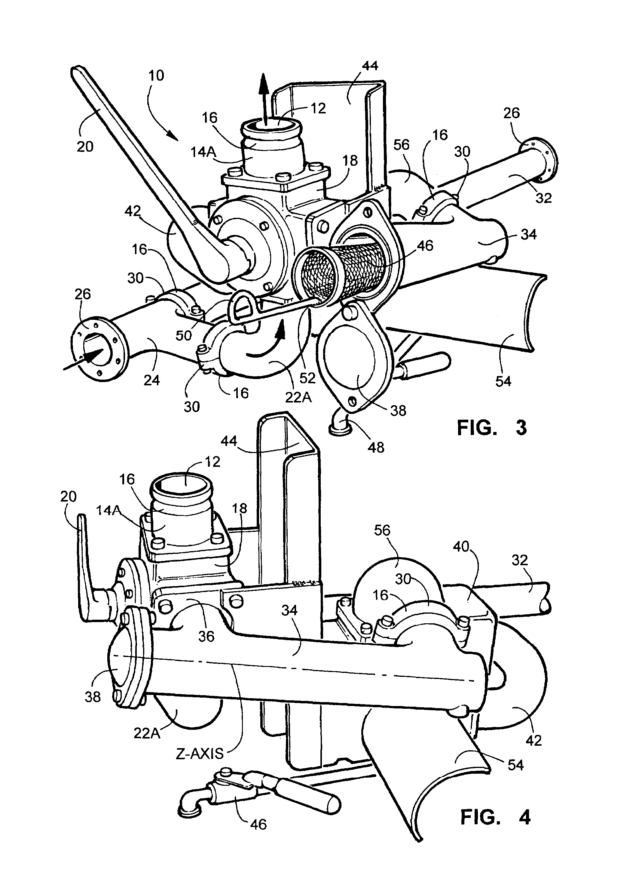
[0050]For a fuller understanding of the nature and objects of the invention, reference should be had to the following detailed description taken in conjunction with the accompanying drawings which are incorporated in and form a part of this specification, illustrating embodiments of the invention and together with the description, serve to explain the principles of this invention. There is seen in FIG. 1 a perspective view of the left side of the manual bulk liquid pump control and distribution system 10. This view illustrates the directional discharge flow of the bulk liquid with arrows having the intake orifice 12 in the flanged coupling 14A with a flexible victaulic coupling means 16 at the top of the flow reversing two-way valve 18. The flow reversing two-way valve 18 is shown with the valve handle 20 to the right in the discharge position. At the bottom of the flow reversing two-way valve 18, the discharge is made through a 90-degree elbow 22 connected to a T-section 24 having ...


PUM

PropertyMeasurementUnit
flow rateaaaaaaaaaa
inclined angleaaaaaaaaaa
flexibilityaaaaaaaaaa

Abstract

The present invention is directed to a manual bulk liquid pump control and distribution system that utilizes a single-handle manual operation for direction of flow and speed, along with providing a neutral position for standby. The system can be operated at a rate of 0 to 250 gallons per minute and be reversed with a single motion of the operating handle. The pump operates in one direction at a fixed RPM, resulting in longer pump life and safer operation. For added safety, the system utilizes the pump's relief valve for both discharge and suction operation. It has the ability of sucking the liquid out of the lines and hoses after each transfer operation. This system has an aluminum flow-reversing valve or two-way valve at the center of the design. This valve allows the flow of the product to be precisely controlled in either direction, along with the flow rate and pressure. This gives the operator the ability to control the product regardless of viscosity or volume. The system has been designed with pressure-tested manifolds and custom design brackets along with a sampling valve and an easily accessible angled strainer basket. The design allows for safe and convenient pump operation as well as for the proper handling of liquids during environmentally sensitive times.

Description

FIELD OF THE INVENTION[0001]This invention relates to the field of controlling the directional flow of bulk liquids. Bulk liquids are generally held in large containment vessels to be stored or transported. This patent deals with the precise control and distribution of liquids from these containment vessels along with the capability of pumping liquid back into the containment vessel by the means of suction. Additionally this patent deals with a unique method of removing any excess liquid from the hoses and lines in the system to insure that no liquid is spilled on the ground or retained within the hoses.[0002]Existing methods of pumping and siphoning bulk liquids has in the past been cumbersome where quantities of the liquid are left within the pump, hoses and distribution lines and this liquid is often spilled onto the ground. A great amount of the bulk liquid is in the form of chemicals, fuel and oil products that produce an environmental hazard when spilled. The Environmental Pro...

Claims


Application Information

Patent Timeline
Patent Type & Authority Patents(United States)
IPC IPC(8): B65B1/04
CPCF04B49/22F04B53/16F04D15/0016Y10T137/3109Y10T137/85994
Inventor PALMER, DAVID
Owner SAFETY PUMPING SYST
Why Eureka
Try Eureka