Rotating shaft scavenging scoop

a technology of rotating shafts and scoops, which is applied in the direction of bearings, roller bearings, air transportation, etc., can solve the problems of increasing the weight of the engine and the cost of operation

Active Publication Date: 2006-10-24
PRATT & WHITNEY CANADA CORP
View PDF19 Cites 32 Cited by
  • Summary
  • Abstract
  • Description
  • Claims
  • Application Information

AI Technical Summary

Benefits of technology

[0010]In accordance with a further general aspect of the present invention, there is provided a gas turbine engine comprising a compressor section, a combustor and a turbine section in serial flow communication with one another, a main rotating shaft supported by a bearing assembly, and a scavenge system for the bearing assembly, the scavenge system comprising a scavenging passage extending axially through said main rotating shaft, and at least one inlet hole defined in said main rotating shaft and in flow communication with said scavenging passage, said at least one inlet hole extending at an angle to a radius of the main rotating shaft to thereby cause oil about the rotating shaft to be drawn into said scavenging passage in said main shaft via said at least one inlet hole as said main shaft rotates.

Problems solved by technology

Oil scavenging systems typically rely on a simple pressure imbalance to direct the used oil into collection tubes for transport to a main oil pump of the oil treatment system.
However, such special pumps and vanes increase the weight of the engine and thus the costs of operation.

Method used


Image

  • Rotating shaft scavenging scoop
  • Rotating shaft scavenging scoop
  • Rotating shaft scavenging scoop

Examples


Embodiment Construction

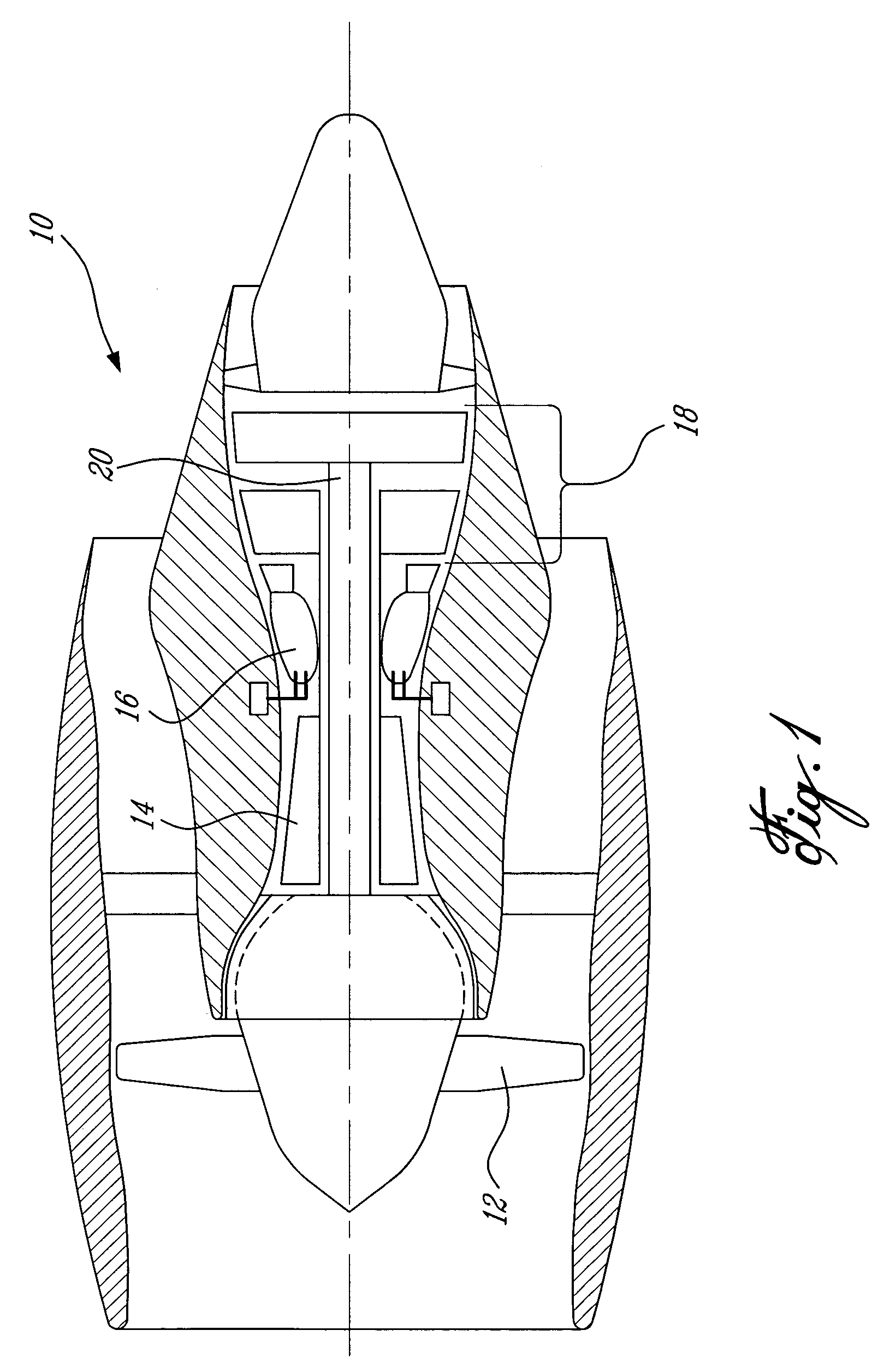
[0017]FIG. 1 illustrates a gas turbine engine 10 of a type preferably provided for use in subsonic flight, generally comprising in serial flow communication a fan 12 through which ambient air is propelled, a multistage compressor 14 for pressurizing the air, a combustor 16 in which the compressed air is mixed with fuel and ignited for generating an annular stream of hot combustion gases, and a turbine section 18 for extracting energy from the combustion gases. A rotating shaft 20 extends within the engine 10 and transfers energy from the turbine section 18 to the compressor 14 and the fan 12.

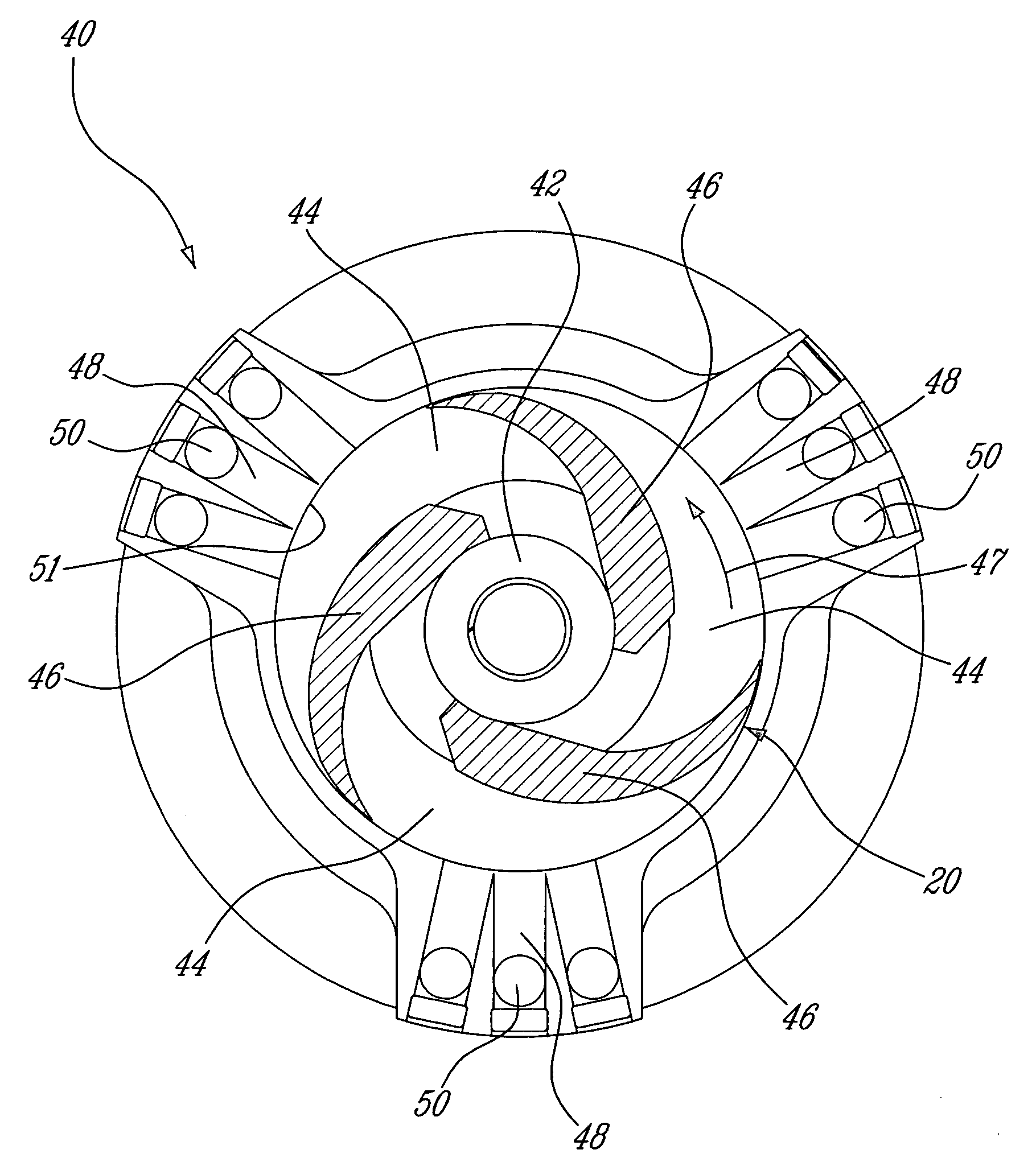
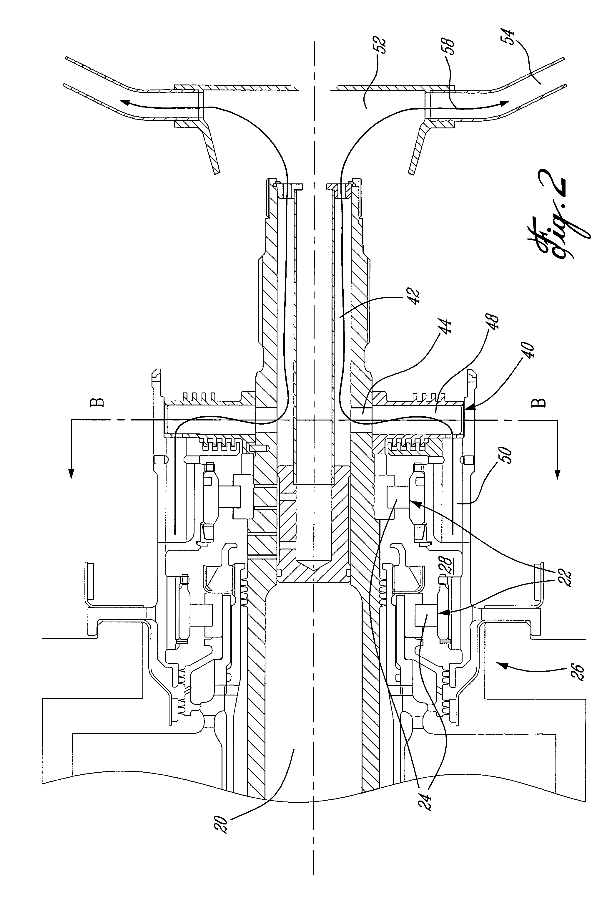
[0018]Referring to FIG. 2, the rotating shaft 20 is supported by a plurality of annular bearing assemblies 22, as well known in the art. Each annular bearing assembly 22 comprises a series of roller bearings 24 located in a bearing compartment 26. The bearing compartment 26 is defined such that each bearing assembly 22 is located within an annular oil cavity 28. The annular oil cavity 28 contain...


PUM


Abstract

A bearing scavenge system comprises a scavenging passage extending axially through a rotating shaft supported by the bearing assembly. Oil and air are drawn from an oil cavity of the bearing assembly and evacuated through the rotating shaft as the shaft rotates.

Description

BACKGROUND OF THE INVENTION[0001]1. Field of the Invention[0002]The present invention generally relates to gas turbine engines and, more particularly, to oil scavenging systems.[0003]2. Description of the Prior Art[0004]Proper scavenging of used oil in bearing assemblies is essential to prevent overheating and premature wear of gas turbine engine mechanical parts. The used oil is usually circulated to an oil treatment system to remove air and particles therefrom before being returned to the bearing assemblies.[0005]Oil scavenging systems typically rely on a simple pressure imbalance to direct the used oil into collection tubes for transport to a main oil pump of the oil treatment system. More efficient systems have been devised, employing special pumps or spinning vanes to improve the used oil circulation. However, such special pumps and vanes increase the weight of the engine and thus the costs of operation.[0006]Accordingly, there is a need for an efficient scavenge system for a b...

Claims


Application Information

Patent Timeline
Patent Type & Authority Patents(United States)
IPC IPC(8): F01M11/02F01D25/16F01D25/18F02C7/06F16C33/66
CPCF01D25/16F01D25/18Y02T50/671F05D2260/60F05D2260/602F16C2360/23F16C33/6685F16C19/26Y02T50/60
Inventor GEKHT, EUGENEHASLAM-JONES, THOMAS FRANCISLEGARE, PIERRE-YVES
Owner PRATT & WHITNEY CANADA CORP
Why Eureka
Try Eureka