Liquid cartridge

a liquid cartridge and nozzle opening technology, applied in printing and other directions, can solve the problems of complicated structure of the holder or liquid emission cartridge, adversely affecting the ink-ejection characteristics, and undetected meniscus at the nozzle opening of the ink-jet head, and achieve the effect of simple configuration

Active Publication Date: 2006-10-24
SEIKO EPSON CORP
View PDF35 Cites 47 Cited by
  • Summary
  • Abstract
  • Description
  • Claims
  • Application Information

AI Technical Summary

Benefits of technology

[0038]According to the sixth aspect of the present invention, there is provided a liquid cartridge for supplying liquid to a liquid ejecting apparatus when mounted thereon. The liquid cartridge includes: a liquid accommodating chamber; a supply portion for supplying liquid accommodated in the liquid accommodating chamber to the liquid ejecting apparatus; an atmospheric valve selectively opening and sealing a communication hole through which the liquid accommodating chamber communicates with ambient air; and a biasing member for biasing the atmospheric valve toward the communication hole for sealing the communication hole. Biasing force of the biasing member is determined so that the atmospheric valve opens the communication hole when the liquid cartridge with the liquid accommodating chamber, which is packed and sealed in a vacuum package under a negative pressure lower than atmospheric pressure, is exposed to atmosphere by opening the package. Accordingly, since the atmospheric valve opens the communication hole once so that the liquid accommodating chamber is in communication with ambient air when the pressure in the liquid accommodating chamber of the liquid cartridge is lower than atmospheric pressure, the difference between pressure in the liquid accommodating chamber and atmospheric pressure can be reduced. Therefore, when the liquid cartridge is mounted in the liquid ejecting apparatus, the liquid cartridge is prevented from drawing the liquid from the liquid ejecting apparatus.
[0039]The biasing member of the liquid cartridge may include a spring. Based on the biasing force of the spring used as the biasing member, how much the pressure difference between the liquid accommodating chamber and atmosphere is to be reduced is adjustable. Moreover, the spring may bias the

Problems solved by technology

Therefore, meniscus at a nozzle opening of the ink-jet head may be undesirably drawn toward the cartridge.
This may adversely affect the ink-ejection characteristics.
However, this structure has a p

Method used


Image

  • Liquid cartridge
  • Liquid cartridge
  • Liquid cartridge

Examples


Embodiment Construction

[0072]The invention will now be described based on the preferred embodiments, which do not intend to limit the scope of the present invention, but exemplify the invention. All of the features and the combinations thereof described in the embodiment are not necessarily essential to the invention.

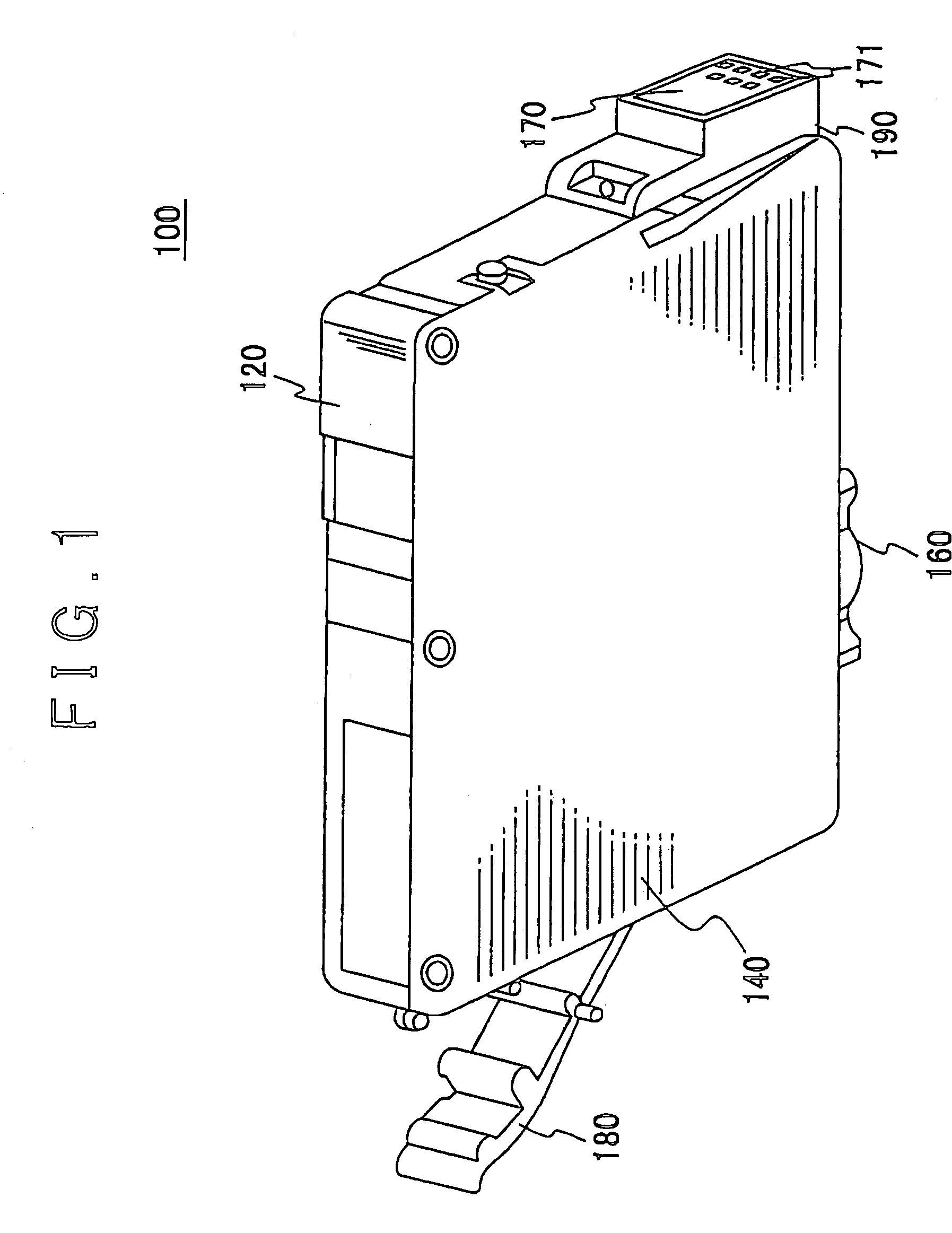
[0073]FIG. 1 is a front perspective view of an ink cartridge 100 of an ink-jet recording apparatus as an exemplary liquid cartridge suitable for supplying liquid to a liquid ejection head of a liquid ejecting apparatus. FIG. 1 shows the structure of the ink cartridge 100 seen obliquely from above.

[0074]The liquid ejection head of the liquid ejecting apparatus of the present invention includes not only the ink-jet head of the ink-jet recording apparatus but also a color-material ejecting head used for fabrication of a color filter for a liquid crystal display or the like, an electrode-material (conductive paste) emitting head used for forming an electrode in an organic EL display or a field-em...


PUM


Abstract

A liquid cartridge is provided that supplies liquid to a liquid ejecting apparatus by being mounted in the liquid ejecting apparatus. The liquid cartridge includes a cartridge body having a side face in which an opening is formed; and a flexible film for forming an ink accommodating chamber that is a closed space for accommodating the liquid, with the cartridge body by covering the opening of the cartridge body. The flexible film is caused to deform toward the ink accommodating chamber by atmospheric pressure that acts on the flexible film when the liquid cartridge is got out from a vacuum bag in which the liquid cartridge is packaged, thereby increasing the pressure in the ink accommodating chamber.

Description

[0001]This patent application claims priority from Japanese patent applications Nos. 2002-358762 filed on Dec. 10, 2002, 2002-358763 filed on Dec. 10, 2002, 2003-012845 filed on Jan. 21, 2003, 2003-012846 filed on Jan. 21, 2003, 2003-196298 filed on Jul. 14, 2003, 2003-301246 filed on Aug. 26, 2003, 2003-304171 filed on Aug. 28, 2003, and 2003-402665 filed on Dec. 2, 2003, the contents of which are incorporated herein by reference.BACKGROUND OF THE INVENTION[0002]1. Field of the Invention[0003]The present invention relates to a liquid cartridge. More particularly, the present invention relates to a liquid cartridge for accommodating liquid while maintaining a negative pressure by means of a differential pressure regulating valve and supplying the liquid to a liquid ejection head via a supply portion thereof while keeping a constant negative pressure.[0004]2. Description of the Related Art[0005]An ink cartridge for supplying ink while keeping the pressure at an ink supply port to be ...

Claims


Application Information

Patent Timeline
IPC IPC(8): B41J2/175
CPCB41J2/17513B41J2/17556B41J2/17559B41J2/17596
Inventor TOBA, KOICHISHINADA, SATOSHISAKAI, YASUTOITO, KENJIICHIHASHI, AKIRASEKI, YUICHIKITAZAWA, AKIHIKOISHIZAWA, TAKU
Owner SEIKO EPSON CORP
Why Eureka
Try Eureka