Method and device for controlling photovoltaic inverter, and feed water device

a photovoltaic inverter and photovoltaic technology, applied in the direction of motor/generator/converter stopper, dynamo-electric converter control, instruments, etc., can solve the problems of motor b>3/b> reducing its speed and consequently power consumption, settling time for mppt control, and response time accompanying a rapid change in the amount of insolation, so as to improve the responsiveness to controlling operations and improve the stability of controlling operation

Inactive Publication Date: 2006-10-24
FUJI ELECTRIC CO LTD +1
View PDF40 Cites 257 Cited by
  • Summary
  • Abstract
  • Description
  • Claims
  • Application Information

AI Technical Summary

Benefits of technology

[0023]According to the present invention, in allowing the photovoltaic inverter to variable-speed control the motor fed with power from solar cells, the monitoring of changes in the terminal voltage of the solar cells enables to grasp changes in the amount of insolation to the solar cell, to shift promptly to the new maximum power points of the solar cells and improve the stability of the controlling operation in the vicinity of the maximum power point.
[0024]In addition, for example, in variable-speed controlling a motor for driving pumps and fans, it is possible to improve the responsiveness to controlling operations by noting that the power required by the motor is proportional to the cube of the rotational speed and by correcting the acceleration and deceleration times of the motor based on that value.

Problems solved by technology

As a result, the motor 3 reduces its speed and consequently its power consumption, and the operating point shifts to the side of the maximum power point of the solar cell.
And when the respective integrating time of the + and − polarities is set at a longer value in order to reduce this fluctuation, a new problem arises in that the settling time for the MPPT control and the response time accompanying a rapid change in the amount of insolation grow longer.

Method used


Image

  • Method and device for controlling photovoltaic inverter, and feed water device
  • Method and device for controlling photovoltaic inverter, and feed water device
  • Method and device for controlling photovoltaic inverter, and feed water device

Examples


Embodiment Construction

[0034]The embodiment of the present invention shown in the figures will be described below.

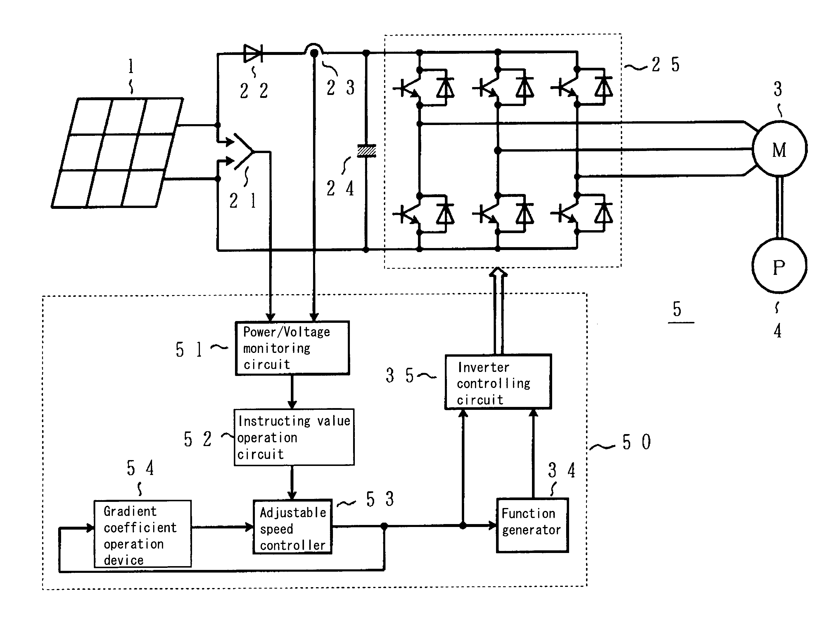
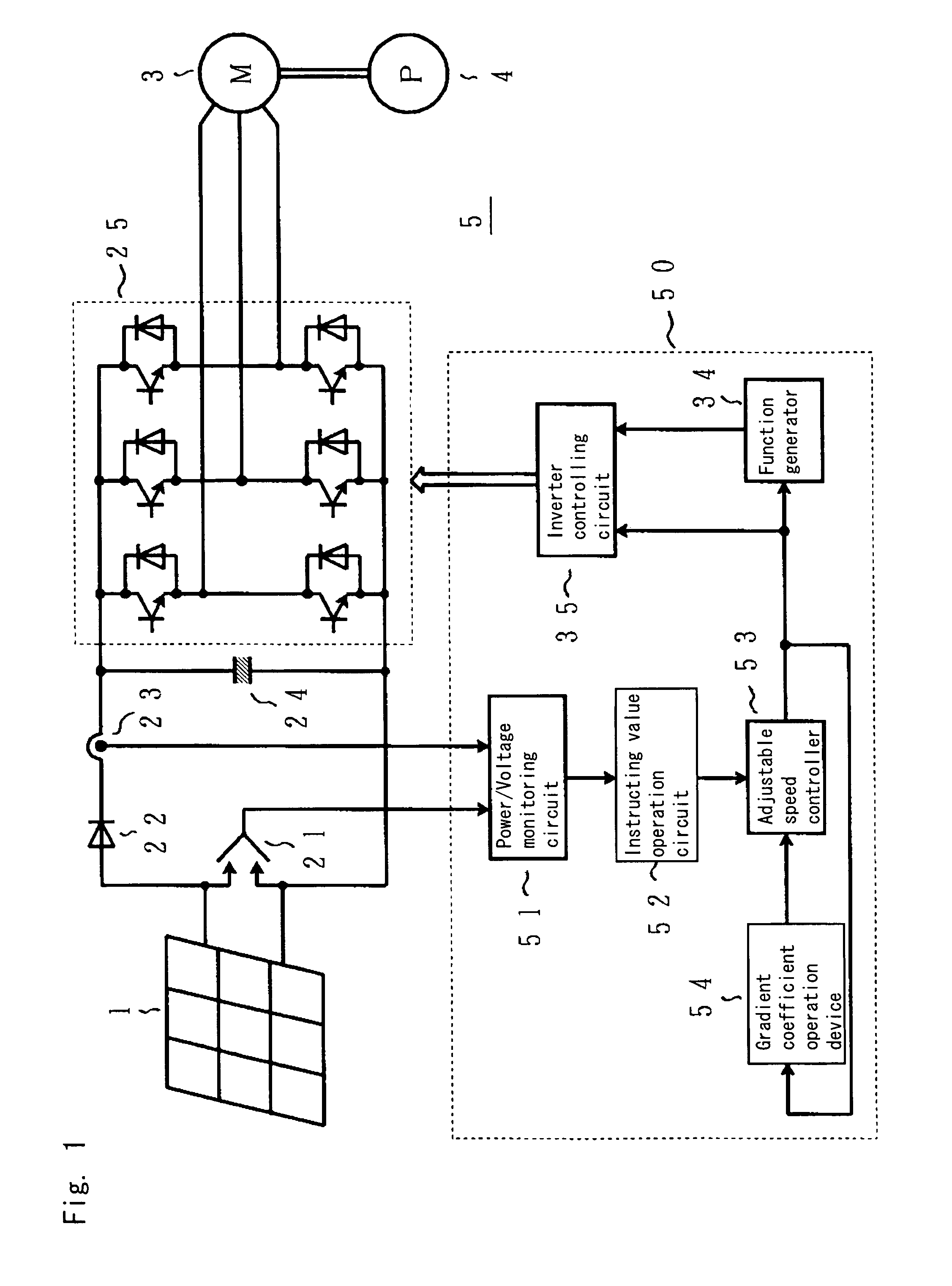
[0035]FIG. 1 is a circuit diagram of a photovoltaic inverter showing an embodiment of the present invention, and the components having the same function as the conventional circuits shown in FIG. 8 are indicated by the same codes.

[0036]In other words, the photovoltaic inverter 5 shown in FIG. 1 includes a controlling device 50 in place of the controlling device 26 of the conventional photovoltaic inverter 2 shown in FIG. 8.

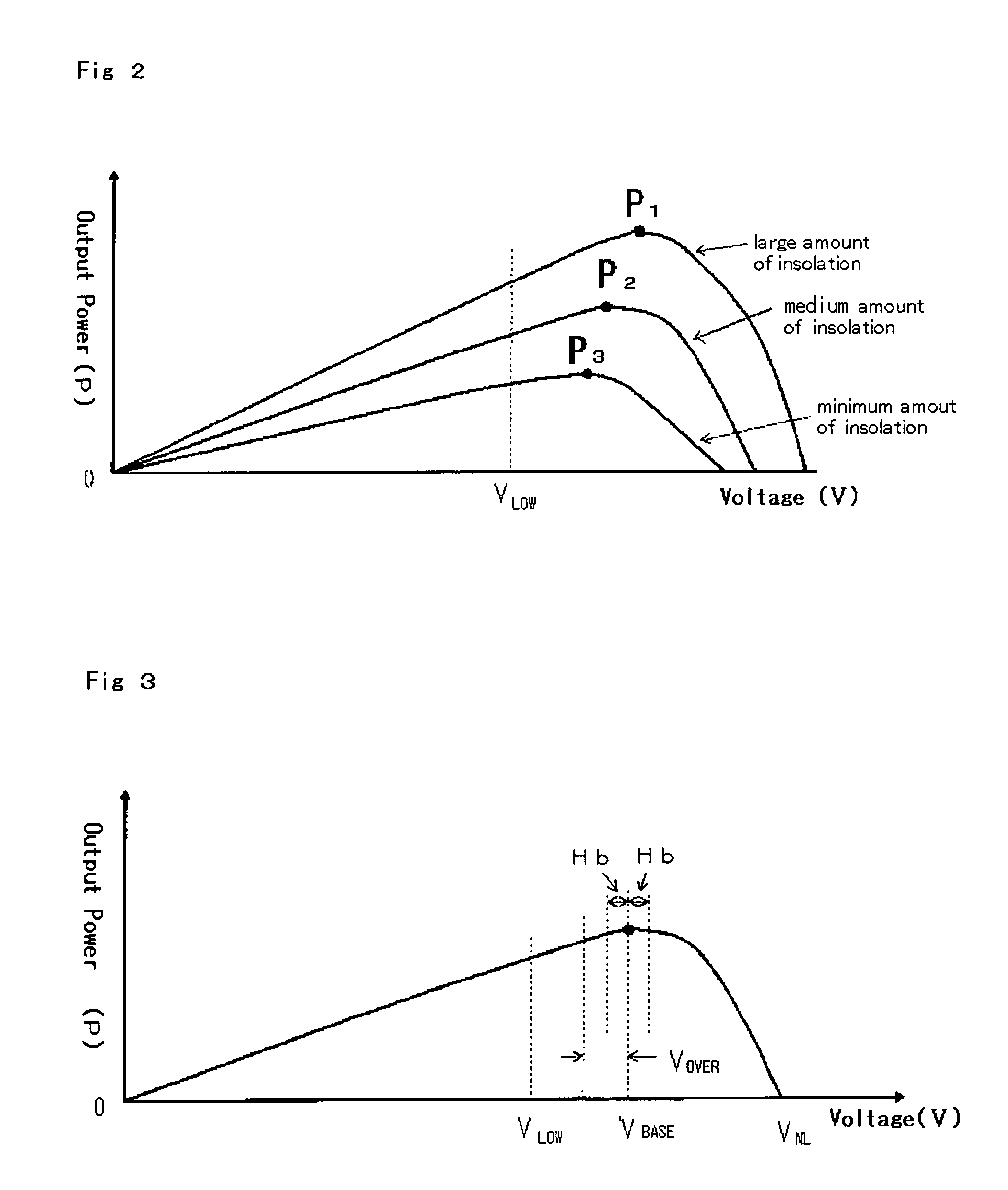
[0037]The controlling device 50 is composed of, in addition to a function generator 34 and an inverter controlling circuit 35 having the same functions as the conventional device, a newly added power and voltage monitoring circuit 51, an instructing value operation circuit 52, an adjustable speed controller 53 and a gradient coefficient operation device 54. And as each of the solar cells 1 have individually a voltage−power (V−P) characteristic that varies as shown in FIG. 2 ...


PUM


Abstract

A photovoltaic inverter control method includes steps of monitoring a variation in output voltage of a solar battery by a power and voltage monitoring circuit (51) and, when the variation occurs, accelerating or decelerating an electric motor (3) to maximize the output voltage of the solar battery (1), whereby the electric motor for driving, for example, a pump and a fan by the solar battery as a power source can be driven by a photovoltaic inverter always at the maximum power point of the solar battery.

Description

TECHNICAL FIELD[0001]The present invention relates to a method of controlling a photovoltaic inverter for converting and controlling DC power supplied by solar cells into AC power (hereinafter referred to as “photovoltaic inverter”) and for variable-speed controlling an AC motor by making the operating point of the solar cells to follow the maximum power point to drive the motor, and to a water feeding device for feeding water by, for example, driving a pump and a fan with a motor variable speed-controlled by means of the method and device for controlling a photovoltaic inverter for variable-speed controlling a motor for driving a pump, a fan and the like.BACKGROUND ART[0002]The solar cell has a voltage (V)−power (P) characteristics wherein power tends to increase as the amount of insolation increases as shown in FIG. 7 when the incident amount of insolation is taken as a parameter, provided that in FIG. 7 Pa, Pb, and Pc represent the maximum power points in the respective amount of...

Claims


Application Information

Patent Timeline
Patent Type & Authority Patents(United States)
IPC IPC(8): G05F1/67G05F5/00H02J7/35H02M7/5387H02P27/06
CPCG05F1/67H02J7/35H02M7/53875H02P27/06H02M2001/0022Y02E10/566Y02E10/58Y10S323/906Y02E10/56H02M1/0022
Inventor MINAMI, MASAHIROICHIKAWA, HIROAKIKAWAI, MASAHITOMURAI, YUKIONAKAJIMA, KAORU
Owner FUJI ELECTRIC CO LTD
Why Eureka
Try Eureka