Method and apparatus for an output buffer with dynamic impedance control

a dynamic impedance control and output buffer technology, applied in the field of output buffers, can solve problems such as limiting the range of loads the output can effectively drive, presenting a problem, and presenting a problem

Active Publication Date: 2006-10-24
INTEGRATED DEVICE TECH INC
View PDF10 Cites 96 Cited by
  • Summary
  • Abstract
  • Description
  • Claims
  • Application Information

AI Technical Summary

Problems solved by technology

This presents a problem.
However, the approach as illustrated in FIG. 1 has a fixed threshold which limits the range of loads the output can effectively drive.
This may present a problem.

Method used


Image

  • Method and apparatus for an output buffer with dynamic impedance control
  • Method and apparatus for an output buffer with dynamic impedance control
  • Method and apparatus for an output buffer with dynamic impedance control

Examples


Embodiment Construction

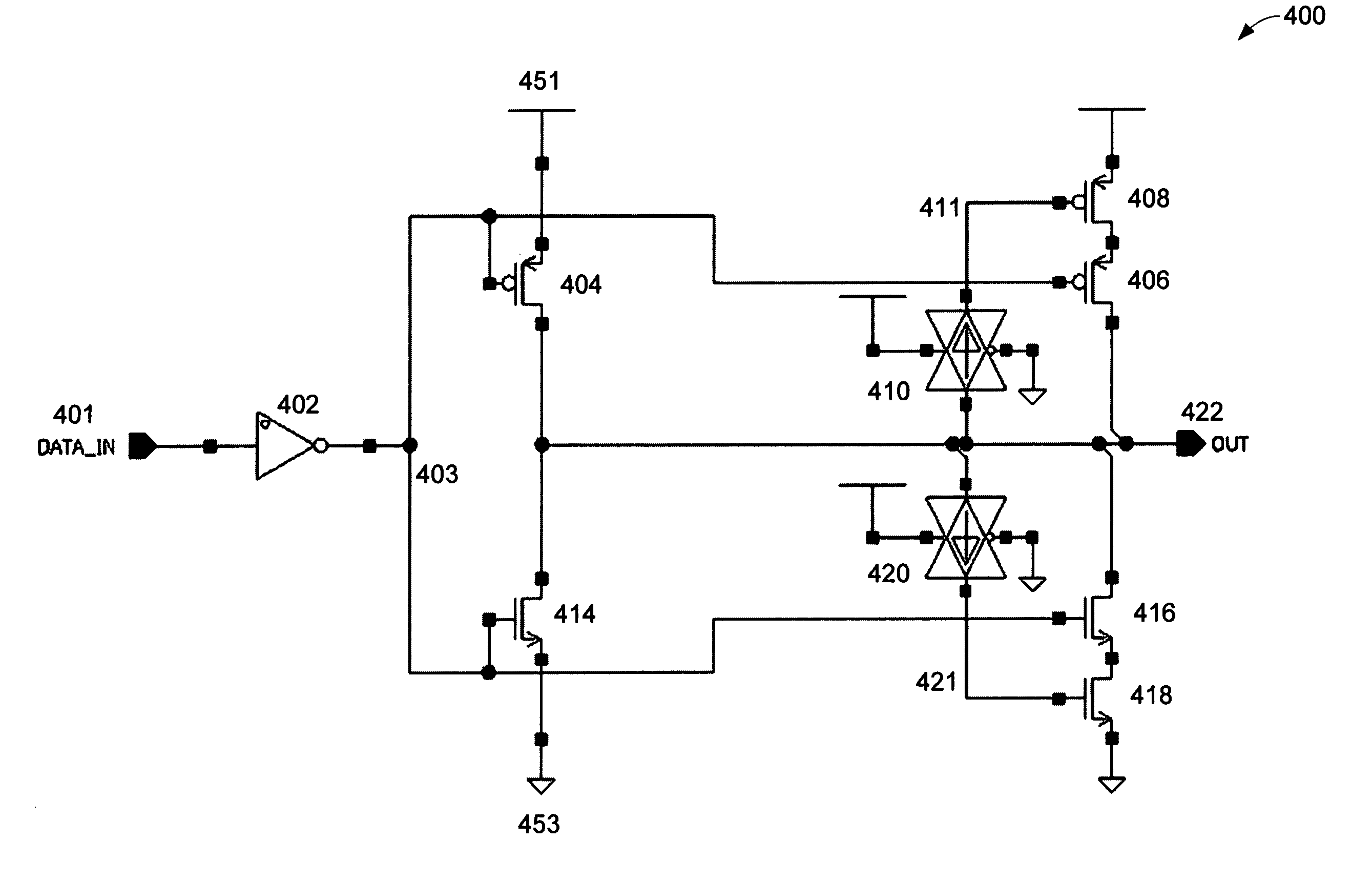
[0015]The invention, as exemplified in various embodiments, illustrates how dynamic impedance control may be achieved. In one embodiment of the invention, an output buffer implements a dynamic impedance control to limit overshoot and undershoot when driving unterminated loads. In one embodiment of the invention, the impedance control is implemented with cascoded output drivers.

[0016]FIG. 4 illustrates one embodiment of the invention used in an output buffer 400. Here, in a simple form of the invention, the gate closest to the output (at transistor 406, and 416) is switched with the inverse data (403), and the cascoded gate (at transistor 408, and 418) which controls impedance is connected to the output via a resistive element (shown as transmission gates (410, and 420) in the schematic); thus the impedance-control device (transistor 408, and 418) is gradually switched ‘off’ as the output (422) swings towards its final value.

[0017]FIG. 4 is now discussed in detail. 401 represents a d...


PUM


Abstract

A method and apparatus for an output buffer with dynamic impedance control have been disclosed.

Description

FIELD OF THE INVENTION [0001]The present invention pertains to output buffers. More particularly, the present invention relates to a method and apparatus for an output buffer with dynamic impedance control.BACKGROUND OF THE INVENTION [0002]Output buffers are an integral part of electronics. Their use is wide and diverse. They are used to drive a variety of other devices both active and passive, for example, logic, microprocessors, bus clocks, resistors, capacitors, backplanes, etc. When driving such a variety of devices and depending upon the load presented to the output buffer it is possible to have effects which may not be wanted. For example, ringing, overshoot, undershoot, EMI (electromagnetic interference), etc. This presents a problem.[0003]For example, FIG. 1 illustrates one current approach 100 having a dynamic output control. One of skill in the art will recognize that FIG. 1 uses a level-detect circuit (the feedback inverters connected at the output) to determine when the ...

Claims


Application Information

Patent Timeline
Patent Type & Authority Patents(United States)
IPC IPC(8): H03D13/00
CPCH03K17/167H03K19/00361
Inventor MCRAE, DUNCANHAYTER, RUSSELL
Owner INTEGRATED DEVICE TECH INC
Why Eureka
Try Eureka