Dynamic Impedance Matching Network and Method for Matching an Impedance Between a Source and a Load

a technology of impedance matching and network, applied in the direction of antenna details, waveguide type devices, antennas, etc., can solve the problems of complex algorithms, prone to errors, and difficult algorithms to find the best setting

Inactive Publication Date: 2011-07-07
QUALCOMM TECHNOLOGIES INC
View PDF10 Cites 22 Cited by
  • Summary
  • Abstract
  • Description
  • Claims
  • Application Information

AI Technical Summary

Benefits of technology

[0016]The advantage of elements designed like that is that controlling the impedance of the matching circuit in an orthogonal way is now possible.
[0031]In an embodiment the matching circuit is electrically connected to an antenna. Matching is necessary because the antenna may be used in different environments or may be in contact with other reactances. It may also be possible that the antenna is the antenna of a mobile communication unit and therefore changes its position and orientation. Tuning the tunable reactance elements of the impedance matching circuit according to the invention can perfectly compensate those variations.

Problems solved by technology

Algorithms to find the best setting are therefore not straightforward but may base on lookup-tables and are complex and prone to errors.

Method used


Image

  • Dynamic Impedance Matching Network and Method for Matching an Impedance Between a Source and a Load
  • Dynamic Impedance Matching Network and Method for Matching an Impedance Between a Source and a Load
  • Dynamic Impedance Matching Network and Method for Matching an Impedance Between a Source and a Load

Examples


Embodiment Construction

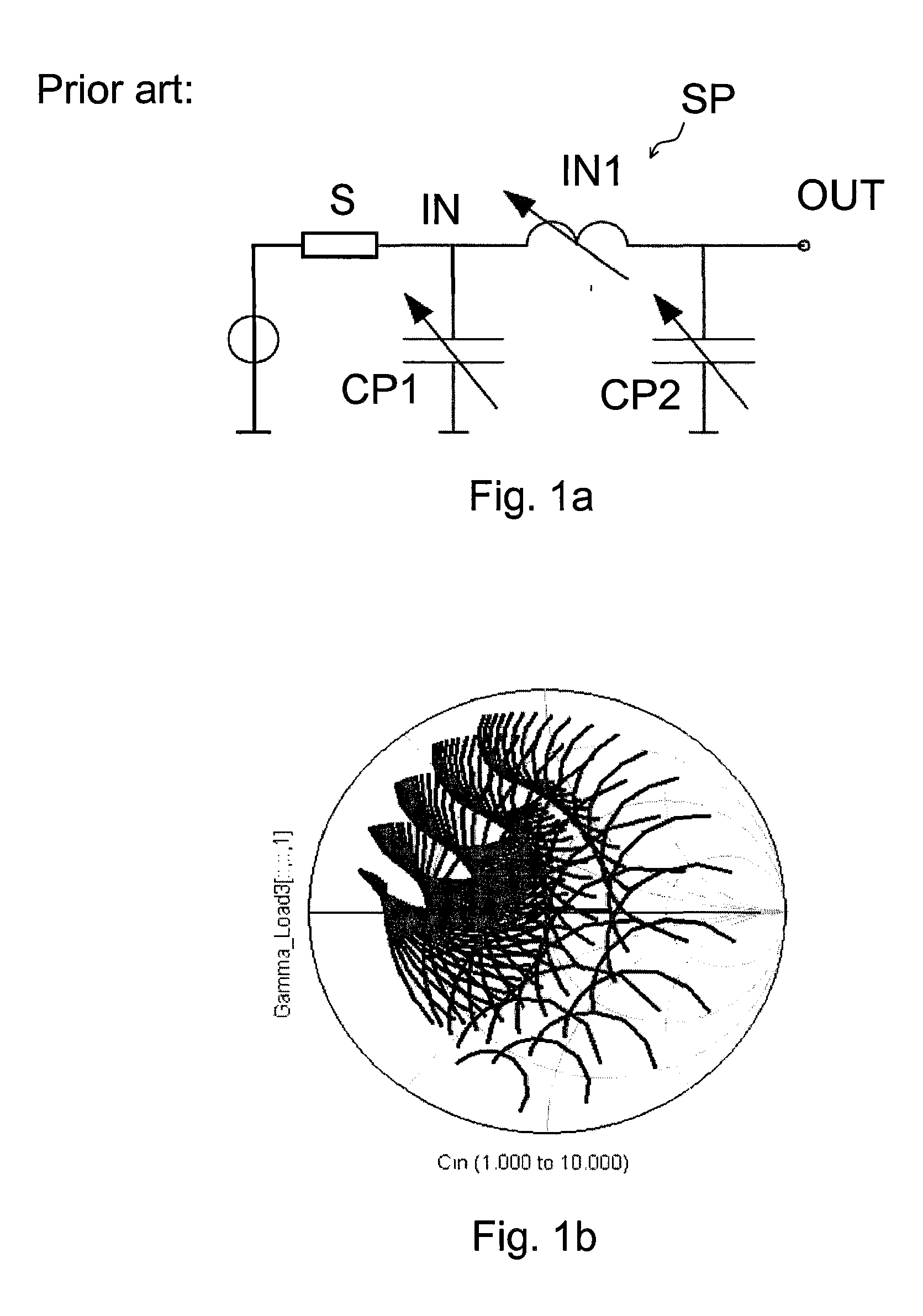
[0068]FIG. 1a illustrates a conventional pi-section network that may be used to match the impedance of a source S that is electrically connected to the input IN of the signal path SP to a device (e.g. an antenna) that may be connected to the output OUT of the signal path SP. In this case the signal path is represented by the tunable inductance element IN1. A capacitance element CP1 electrically connects the input of the signal path IN to ground while another capacitance element CP2 electrically connects the output of the signal path to ground. Both capacitance elements are tunable. Thus there are three degrees of freedom to vary the total impedance of the shown impedance matching circuit leading to the above mentioned problems further discussed in view of FIG. 1b as follows.

[0069]FIG. 1b illustrates the complexity of the impedance dependence of the simple pi-section shown in FIG. 1a. According to the above mentioned equation it is quite difficult to find an algorithm that enables to...


PUM


Abstract

An impedance matching network includes an impedance matching circuit for dynamically matching an impedance between a source and a load. Matching is done by varying the real part and the imaginary part of the impedance of the impedance matching circuit independently.

Description

[0001]This application is a continuation of co-pending International Application No. PCT / EP2009 / 059754, filed Jul. 28, 2009, which designated the United States and was published in English, and which claims priority to European Application No. 08162029.6, filed Aug. 7, 2008, both of which applications are incorporated herein by reference.TECHNICAL FIELD[0002]The present invention relates to a dynamic impedance matching network matching the impedance of an antenna as a load impedance to internal circuits as source impedances such as those used in portable communication devices, for example in mobile phones.BACKGROUND[0003]U.S. Pat. No. 6,845,126 B2 relates to a system for an adaptive antenna impedance matching. The impedance mismatch is determined dynamically by measuring the strength of a signal reflected from an antenna. An impedance matching circuit being electrically connected within the signal path is tuned in order to minimize the Voltage Standing Wave Ratio (VSWR). Tuning can ...

Claims


Application Information

Patent Timeline
Patent Type & Authority Applications(United States)
IPC IPC(8): H03H7/40H01Q1/50
CPCH03H7/40H03H7/38
Inventor DE JONGH, MAURICEBEZOOIJEN, ADRIANUS VAN
Owner QUALCOMM TECHNOLOGIES INC
Why Eureka
Try Eureka