Braking system with two pressure sources, and method for operating a braking system with two pressure sources

a technology of braking system and pressure source, which is applied in the direction of braking system, vehicle sub-unit features, braking components, etc., can solve the problem of not being able to interrupt the active braking function, and achieve the effect of improving function, improving normal function, and being more robust against possible faults

Pending Publication Date: 2021-02-25
CONTINENTAL TEVES AG & CO OHG
View PDF22 Cites 19 Cited by
  • Summary
  • Abstract
  • Description
  • Claims
  • Application Information

AI Technical Summary

Benefits of technology

[0014]It has now been found that this requirement can be fulfilled in that firstly, the electrical and hydraulic independence of the two brake circuits is systematically implemented, and secondly a control of hydraulic components of the two brake circuits by the still functioning components is possible. In this way, the braking system can always execute the functionality of a braking system with a pressure setting device. Via the data interface, each of the two control and regulating units can determine the state of the other unit, and on failure react accordingly and take over the supply to the failed brake circuit.
[0043]A disadvantage of known simulator brake systems is that the closing capacity of so-called pressure switch-on valves can only be monitored poorly. To test this, the pressure switch-on valve must be pressurized from the side facing away from the pressure setting device. This is not possible or only indirectly possible in known braking systems. In the braking system described, such a pressurization for testing the pressure switch-on valves can easily be achieved by means of the respective other pressure setting device, without pressure build-up in the wheel brakes or activation unit. For the corresponding test, the wheel inlet valves are closed so that a hydraulically stiff chamber is created which allows very short test periods.

Problems solved by technology

In particular in braking systems which are provided or optimized for automated driving functions, an uninterrupted provision of the active braking function is necessary.

Method used


Image

  • Braking system with two pressure sources, and method for operating a braking system with two pressure sources
  • Braking system with two pressure sources, and method for operating a braking system with two pressure sources
  • Braking system with two pressure sources, and method for operating a braking system with two pressure sources

Examples


Embodiment Construction

[0049]In all of the figures, identical parts are denoted by the same reference designations.

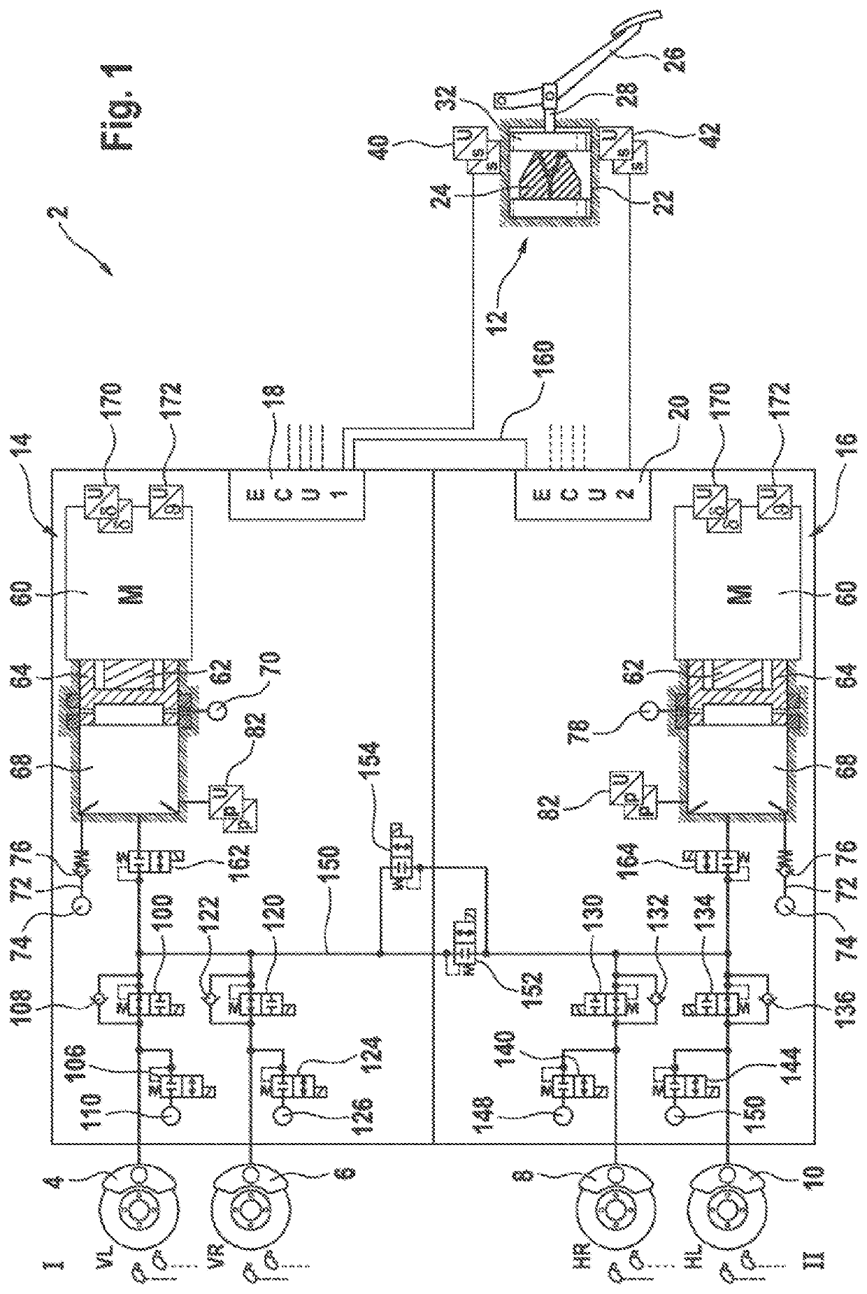
[0050]A braking system 2 shown in FIG. 1 comprises four hydraulically actuatable wheel brakes 4, 6, 8, 10, a pedal feel simulator or simulator 12, two pressure supply devices 14, 16, two electronic control and regulating units 18, 20, a pressure medium reservoir 22 (not shown) under atmospheric pressure.

[0051]The simulator 12 comprises a cylinder 22 in which an elastic simulator element 24 is arranged. A brake pedal 26 is connected to a simulator piston 32 via a piston rod 28, such that actuation of the brake pedal 26 from the rest position presses the simulator piston 32 against a simulator element 24, whereby the driver feels a counter-force. A pedal feel is advantageously simulated in this way. The simulator 12 is of dry design, i.e. it comprises no pressure chamber filled with pressure medium.

[0052]Two preferably redundantly designed travel sensors 40, 42 measure the piston travel of the ...


PUM


Abstract

A braking system including four hydraulically actuatable wheel brakes. A normally closed outlet valve is assigned to each wheel brake and a normally open inlet valve is assigned to each wheel brake. Two pressure supply devices are provided for active pressure build-up in the wheel brakes. A first and a second brake circuit are hydraulically configured with two wheel brakes respectively, wherein in each brake circuit a respective pressure supply device is hydraulically connected to two wheel brakes. A first and a second control and regulating unit are provided, wherein the first control and regulating unit electrically controls the pressure supply device of the first brake circuit, and wherein the second control and regulating unit hydraulically controls the pressure supply device of the second brake circuit, and the two control and regulating units are connected together via a data interface.

Description

CROSS REFERENCE TO RELATED APPLICATIONS[0001]This application is the U.S. National Phase Application of PCT International Application No. PCT / EP2019 / 062509, filed May 15, 2019, which claims priority to German Patent Application No. 10 2018 208 223.5, filed May 24, 2018, the contents of such applications being incorporated by reference herein.FIELD OF THE INVENTION[0002]The invention concerns a braking system comprising four hydraulically actuatable wheel brakes, wherein a normally closed outlet valve is assigned to each wheel brake and a normally open inlet valve is assigned to each wheel brake, wherein two pressure supply devices are provided for active pressure build-up in the wheel brakes, wherein a first and a second brake circuit are hydraulically configured with two wheel brakes respectively, and wherein in each brake circuit a respective pressure supply device is hydraulically connected to two wheel brakes. The invention furthermore relates to a corresponding operating method...

Claims


Application Information

Patent Timeline
Patent Type & Authority Applications(United States)
IPC IPC(8): B60T13/58B60T15/02B60T8/17
CPCB60T13/58B60T15/028B60T8/4081B60T2270/402B60T8/17B60T7/042B60T8/885B60T13/745B60T2220/04B60T2270/403B60T2270/404B60T2270/413B60T2270/82B60T8/326B60Y2400/81B60T13/16B60T13/161
Inventor BESIER, MARCODRUMM, STEFAN
Owner CONTINENTAL TEVES AG & CO OHG
Why Eureka
Try Eureka