Automatic speed reducing ratio-switching apparatus

a technology of automatic speed reduction and ratio switching, which is applied in mechanical devices, fluid gearings, gearing, etc., can solve the problem that the movement speed of the screw shaft cannot be increased to a high speed for expanding operation

Active Publication Date: 2007-05-22
SMC CORP
View PDF10 Cites 17 Cited by
  • Summary
  • Abstract
  • Description
  • Claims
  • Application Information

AI Technical Summary

Benefits of technology

[0008]A general object of the present invention is to provide an automatic speed reducing ratio-switching apparatus which makes it possible to control the torque and transmit the torque at a high speed by automatically switching the speed reducing ratio corresponding to the operation of a displacement member for constructing an actuator.
[0009]A principal object of the present invention is to provide an automatic speed reducing ratio-switching apparatus which makes it possible to reduce the number of parts and decrease the size of the entire apparatus.

Problems solved by technology

Therefore, the movement speed of the screw shaft cannot be increased to a high speed for the expanding operation even when the load torque applied to the electric cylinder is small.

Method used


Image

  • Automatic speed reducing ratio-switching apparatus
  • Automatic speed reducing ratio-switching apparatus
  • Automatic speed reducing ratio-switching apparatus

Examples


first embodiment

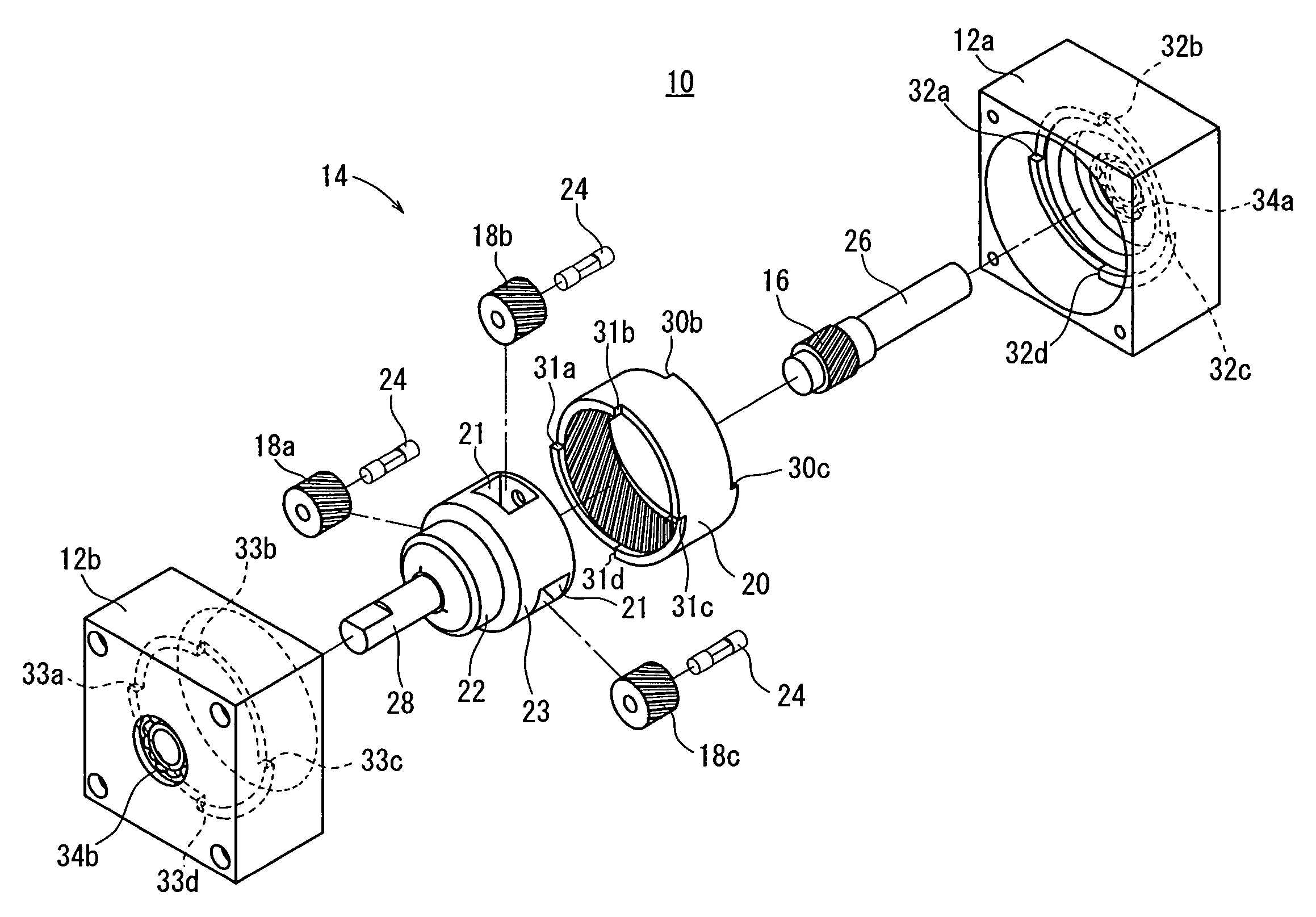
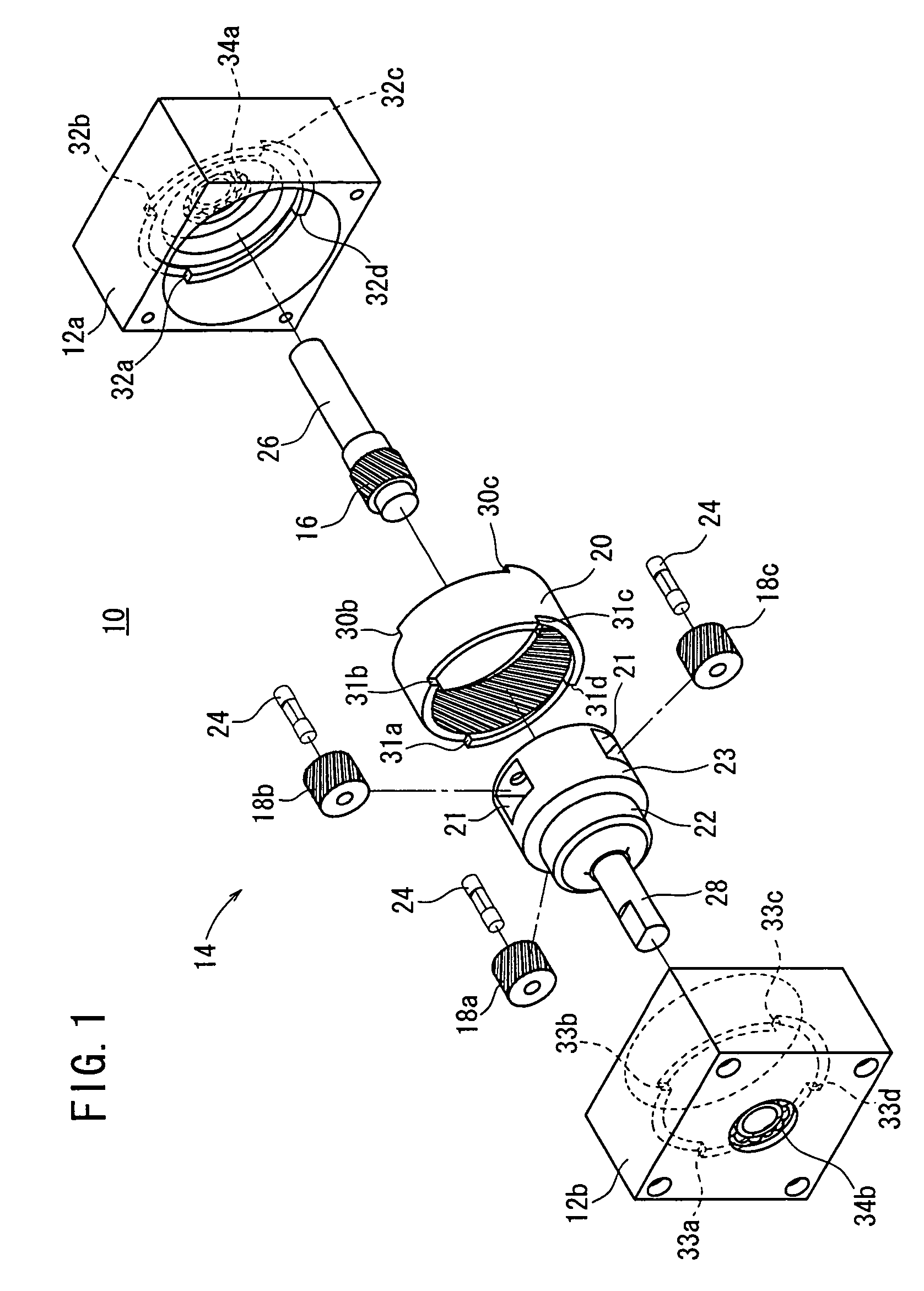
[0046]FIG. 1 shows an exploded perspective view illustrating an automatic speed reducing ratio-switching apparatus according to the present invention. As shown in FIG. 1, the automatic speed reducing ratio-switching apparatus 10 comprises housings 12a, 12b which are constructed by being divided into two parts, and a planetary gear mechanism 14.

[0047]The housing 12a is rectangular in cross section. Lock sections 32a to 32d, which are circular arc-shaped projections to make engagement with internal gear lock receiving sections 30a to 30d as described later on when an internal gear 20 makes parallel displacement in a direction toward an input shaft 26 as described later on, are formed on an inner side of the housing 12a. Further, the housing 12a is provided with a bearing section 34a for rotatably supporting the input shaft 26. The housing 12b is rectangular in cross section in the same manner as the housing 12a. Lock sections 33a to 33d, which are circular arc-shaped projections to ma...

third embodiment

[0081]Accordingly, the automatic speed reducing ratio-switching apparatus 10B may be incorporated into the pressing apparatus 70 shown in FIGS. 15A to 15C. Starting from the state shown in FIG. 15B, when the pressing section 86 is displaced by a predetermined distance toward the workpiece W to make abutment against the workpiece W, and the load, which exceeds the preset torque, is applied from the pressing apparatus 70 via the output shaft 28 to the carrier 22, then the planet gears 18a, 18b, 18c make rotation in the counterclockwise direction which is opposite to the direction of the sun gear 16 without making revolution in accordance with the rotation of the sun gear 16, and the internal gear 20A, which is meshed with the planet gears 18, is rotated in the counterclockwise direction (see FIG. 7). As a result, the thrust force acts on the internal gear 20A, and the internal gear 20A makes parallel displacement in the Z1 direction.

[0082]The internal gear 20A makes the parallel disp...

fourth embodiment

[0085]Next, FIG. 25 shows an automatic speed reducing ratio-switching apparatus 10C according to the present invention. The automatic speed reducing ratio-switching apparatus 10C comprises housings 12a, 12b and a planetary gear mechanism 14B. The planetary gear mechanism 14B is accommodated in the housings 12a, 12b which are assembled in an integrated manner.

[0086]Lock sections 54 having projecting shapes, which are engageable with carrier lock receiving sections 52 as described later on when a carrier 22B makes parallel displacement in the direction toward the input shaft 26, are formed for the housing 12a therein. Lock sections 55 having projecting shapes, which are engageable with carrier lock receiving sections 53 as described later on when the carrier 22B makes parallel displacement in the direction toward the output shaft 28B, are formed for the housing 12b therein. The lock sections 54, 55 have projecting shapes to depict curves in the circumferential direction. A bearing sec...


PUM


Abstract

Helical gears are used for a sun gear, planet gears, and an internal gear. Accordingly, when a load, which exceeds a preset torque, is applied to the internal gear, the internal gear is moved in a direction toward an input shaft or a direction toward an output shaft while making rotation in a direction different from that of the sun gear to automatically switch the speed reducing ratio.

Description

BACKGROUND OF THE INVENTION[0001]1. Field of the Invention[0002]The present invention relates to an automatic speed reducing ratio-switching apparatus capable of automatically switching the speed reducing ratio transmitted from an output shaft to a displacement member of an actuator by using a planetary gear mechanism when a load, which exceeds a predetermined torque, is applied.[0003]2. Description of the Related Art[0004]Those to which the speed reducing ratio-switching mechanism has been hitherto applied include, for example, machine systems such as construction machines. In such a machine system, an electric cylinder is used as an actuator for an expansion / contraction operation system for driving a link mechanism.[0005]In such an electric cylinder, a rotary shaft is connected to an input section of an electric motor in a casing, and a screw shaft is arranged in the rotary shaft. The screw shaft is screwed to a nut member which is rotatably supported in the casing. Two pairs of p...

Claims


Application Information

Patent Timeline
Patent Type & Authority Patents(United States)
IPC IPC(8): F16H47/08F16H3/54F16H61/02
CPCF16H3/54F16H61/0295F16H1/28
Inventor NAGAI, SHIGEKAZUSAITOH, AKIOMASUI, RYUICHIIMAMURA, MASAKI
Owner SMC CORP
Why Eureka
Try Eureka