Automatic speed reducing ratio-switching apparatus
- Summary
- Abstract
- Description
- Claims
- Application Information
AI Technical Summary
Benefits of technology
Problems solved by technology
Method used
Image
Examples
first embodiment
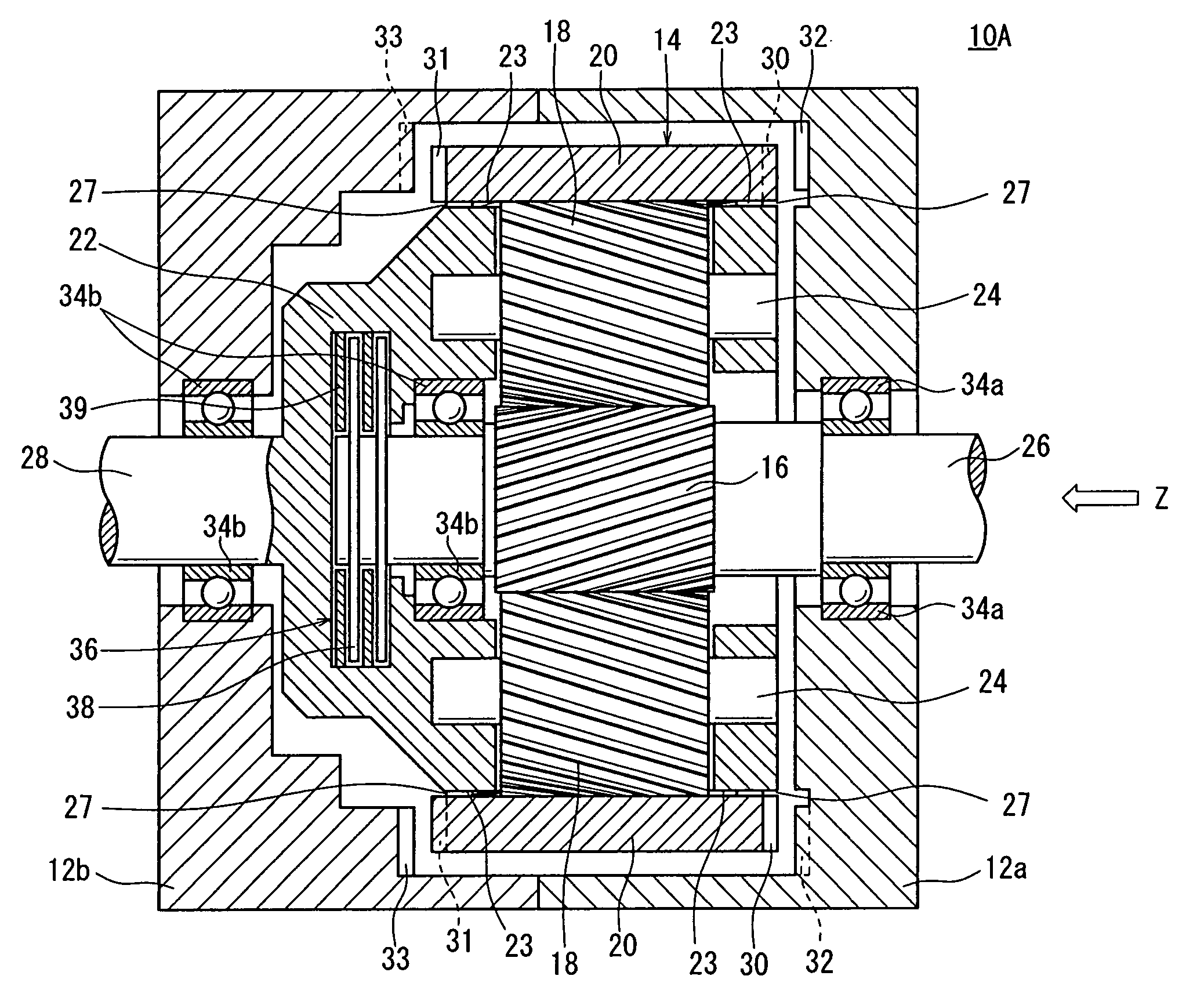
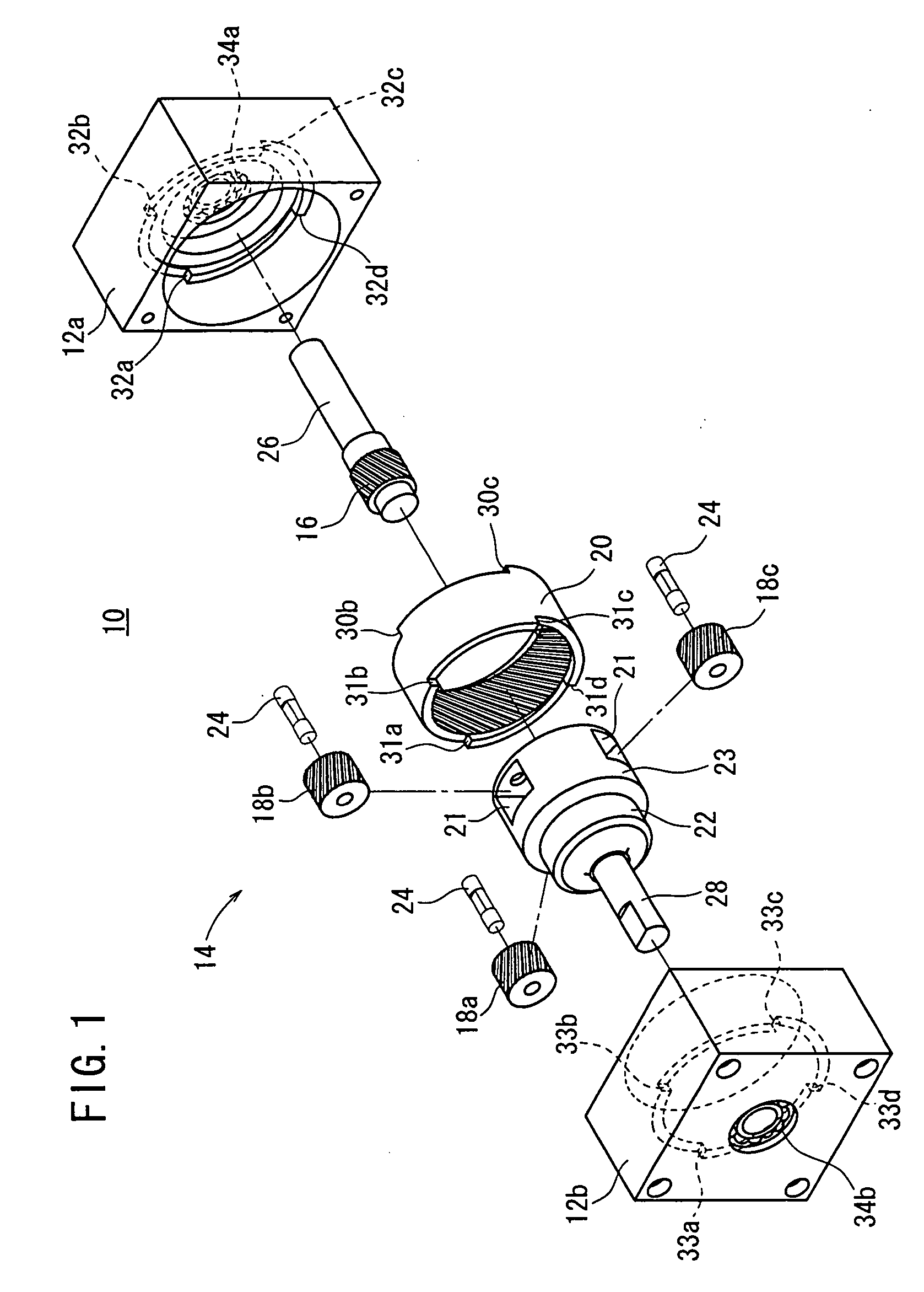
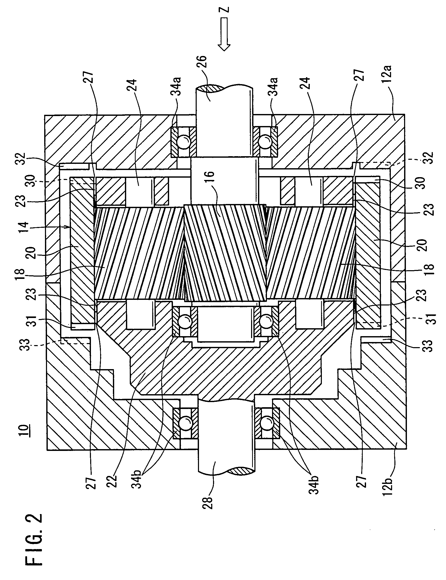
[0046]FIG. 1 shows an exploded perspective view illustrating an automatic speed reducing ratio-switching apparatus according to the present invention. As shown in FIG. 1, the automatic speed reducing ratio-switching apparatus 10 comprises housings 12a, 12b which are constructed by being divided into two parts, and a planetary gear mechanism 14.
[0047] The housing 12a is rectangular in cross section. Lock sections 32a to 32d, which are circular arc-shaped projections to make engagement with internal gear lock receiving sections 30a to 30d as described later on when an internal gear 20 makes parallel displacement in a direction toward an input shaft 26 as described later on, are formed on an inner side of the housing 12a. Further, the housing 12a is provided with a bearing section 34a for rotatably supporting the input shaft 26. The housing 12b is rectangular in cross section in the same manner as the housing 12a. Lock sections 33a to 33d, which are circular arc-shaped projections to m...
third embodiment
[0081] Accordingly, the automatic speed reducing ratio-switching apparatus 10B may be incorporated into the pressing apparatus 70 shown in FIGS. 15A to 15C. Starting from the state shown in FIG. 15B, when the pressing section 86 is displaced by a predetermined distance toward the workpiece W to make abutment against the workpiece W, and the load, which exceeds the preset torque, is applied from the pressing apparatus 70 via the output shaft 28 to the carrier 22, then the planet gears 18a, 18b, 18c make rotation in the counterclockwise direction which is opposite to the direction of the sun gear 16 without making revolution in accordance with the rotation of the sun gear 16, and the internal gear 20A, which is meshed with the planet gears 18, is rotated in the counterclockwise direction (see FIG. 7). As a result, the thrust force acts on the internal gear 20A, and the internal gear 20A makes parallel displacement in the Z1 direction.
[0082] The internal gear 20A makes the parallel di...
fourth embodiment
[0085] Next, FIG. 25 shows an automatic speed reducing ratio-switching apparatus 10C according to the present invention. The automatic speed reducing ratio-switching apparatus 10C comprises housings 12a, 12b and a planetary gear mechanism 14B. The planetary gear mechanism 14B is accommodated in the housings 12a, 12b which are assembled in an integrated manner.
[0086] Lock sections 54 having projecting shapes, which are engageable with carrier lock receiving sections 52 as described later on when a carrier 22B makes parallel displacement in the direction toward the input shaft 26, are formed for the housing 12a therein. Lock sections 55 having projecting shapes, which are engageable with carrier lock receiving sections 53 as described later on when the carrier 22B makes parallel displacement in the direction toward the output shaft 28B, are formed for the housing 12b therein. The lock sections 54, 55 have projecting shapes to depict curves in the circumferential direction. A bearing s...
PUM
 Abstract
Description
Claims
Application Information
 - R&D
- Intellectual Property
- Life Sciences
- Materials
- Tech Scout
- Unparalleled Data Quality
- Higher Quality Content
- 60% Fewer Hallucinations
Browse by: Latest US Patents, China's latest patents, Technical Efficacy Thesaurus, Application Domain, Technology Topic, Popular Technical Reports.
© 2025 PatSnap. All rights reserved.Legal|Privacy policy|Modern Slavery Act Transparency Statement|Sitemap|About US| Contact US: help@patsnap.com


