Two dimension RF location method and apparatus

a location method and apparatus technology, applied in the field of cage telemetry systems, can solve the problems of thwarting efforts to maintain a strict cage location scheme, requiring specific shelving location requirements of cages, and not always practical,

Active Publication Date: 2006-10-24
SIEMENS IND INC +1
View PDF5 Cites 49 Cited by
  • Summary
  • Abstract
  • Description
  • Claims
  • Application Information

AI Technical Summary

Benefits of technology

[0010]The present invention addresses the above-described need, as well as others, by providing a location system and method that determines the two-dimensional location of an object by determining distance-related information between each of two points and the object, which may be an animal cage module, using RF communications. The invention also calculates the two-dimensional location based on the distance related information. Using such a system, the location of an animal cage among a rack of cages, or other grouping of animal cages, may be obtained relatively quickly.

Problems solved by technology

One issue that arises from such an arrangement is the location of particular animals and cages within a room that may contain several racks, each with a number of rows and columns of cages.
However, it is often impractical or at least inconvenient to require specific shelving location requirements of the cages.
The movement of racks, human error and expedience can thwart efforts to maintain a strict cage location scheme.
With a strict “hard-coded” cage location scheme, such a change can require moving an animal out of one cage and into another, which is not always practical.
While this system allows for flexible cage location, it still consumes researcher time noting and recording cage locations within the log.
The log may become cumbersome and difficult to use, and is always subject to human error.
If the cage has been mislocated, or mislogged, the animal's life may be unnecessarily endangered.

Method used


Image

  • Two dimension RF location method and apparatus
  • Two dimension RF location method and apparatus
  • Two dimension RF location method and apparatus

Examples


Embodiment Construction

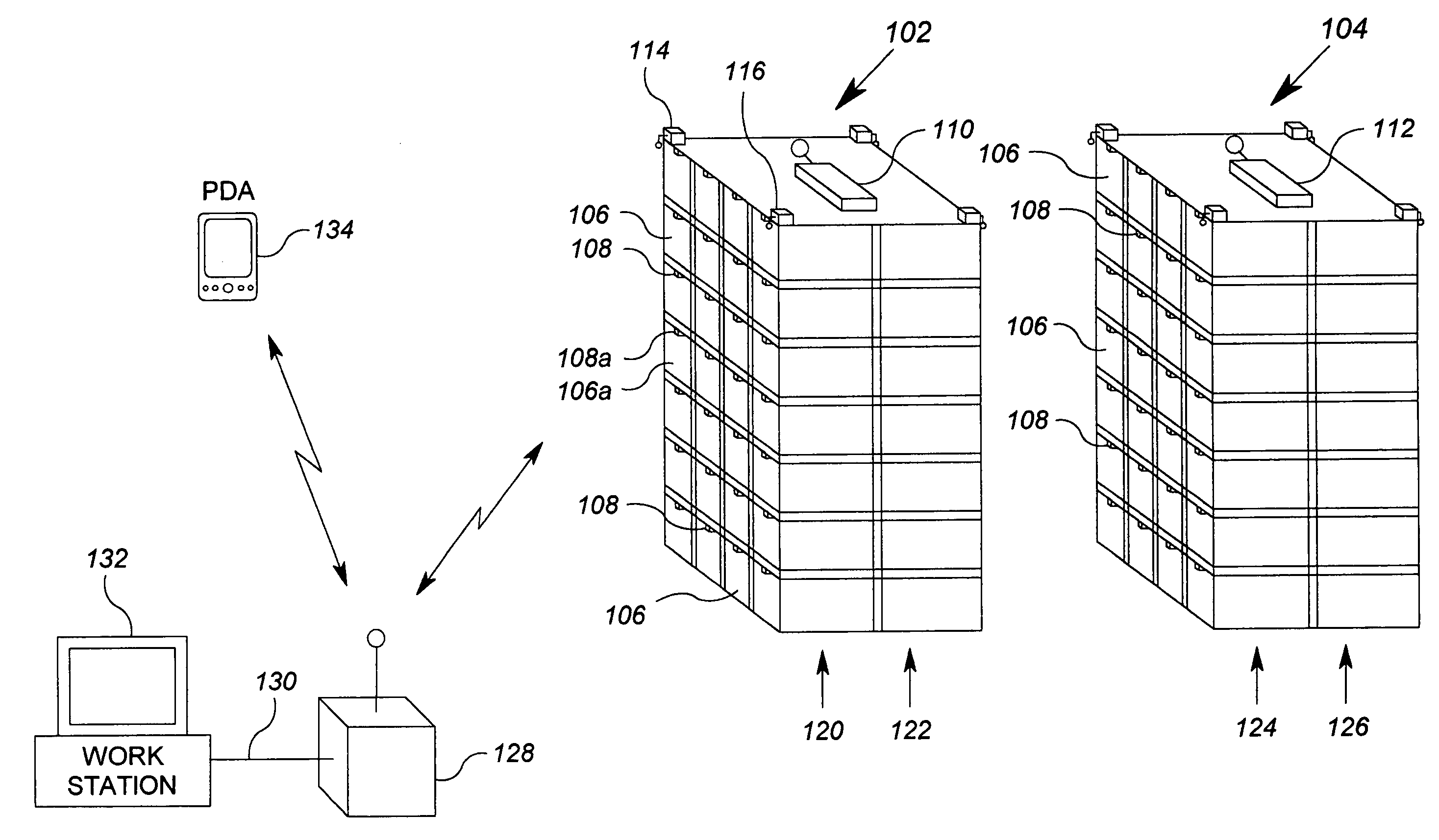
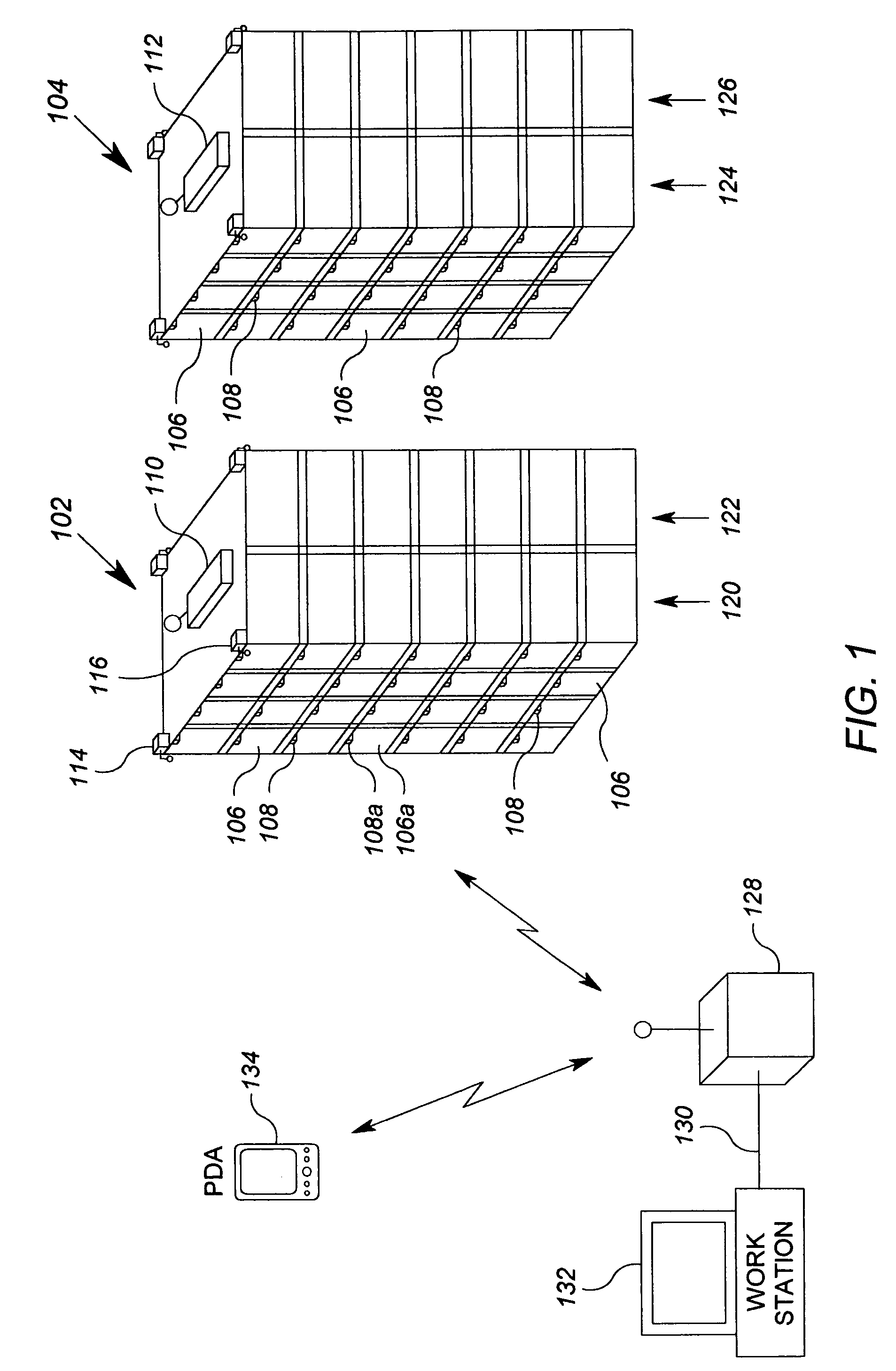
[0027]FIG. 1 shows a representative block diagram of an exemplary cage data system 100 according to various inventive aspects described herein. The cage data system 100 includes a plurality of racks 102, 104, each having a plurality of cages 106. The cages 106 are arranged in rows and columns in the racks 102 and 104. While the precise dimensions of the cages 106 are not important to disclosure of the invention, each cage 106 is an enclosure preferably having a rectangular footprint that has a size typical in the industry for the animal it is meant to contain. Each cage 106, as is known in the art, includes openings at least at the ends thereof to allow for ventilation. In accordance with this embodiment of the invention, each cage 106 also includes a wireless module 108 that is capable of providing telemetry information in conjunction with other elements of the system 100.

[0028]The cage data system 100 also includes a rack data transponder 110 associated with the first rack 102 and...


PUM


Abstract

A system for generating information identifying a two-dimensional location of objects in within a space includes a plurality of wireless modules and first and second transceiver systems. Each of the plurality of wireless modules corresponds to one of the objects. The first and second radio transceiver systems are spaced apart by a predetermined distance and are disposed proximate the space. The first and second radio transceiver systems are operable to selectively transmit a signal to select wireless module, receive a response signal from the select wireless module, and generate first information based on a detected relationship between the selective transmission and the receipt of the response signal. The system further includes a device operable to calculate a two-dimensional location of the select wireless module based on the first information generated by the first radio transceiver system and the first information generated by the second radio transceiver system.

Description

CROSS REFERENCE TO RELATED APPLICATIONS[0001]Cross-reference is made to co-pending U.S. patent application Ser. No. 10 / 951,450, entitled “Cage Telemetry Module and System”, filed Sep. 27, 2004, and to co-pending U.S. patent application Ser. No. 10 / 952,236, entitled “Cage Telemetry System Using Intermediate Transponders”, filed Sep. 27, 2004.FIELD OF THE INVENTION[0002]The present invention relates generally to cage telemetry systems, and more particularly, systems for remotely obtaining sensor and / or location information for one or more cages.BACKGROUND OF THE INVENTION[0003]Research facilities such as universities and other research laboratories often maintain large numbers of animal cages. For relatively small animals, such as rodents, cages may be arranged in racks having several rows and columns of cages. Provision is made for humane conditions for animal safety. To ensure such humane conditions, it is desirable to monitor the conditions in the cage. It is also important to be a...

Claims


Application Information

Patent Timeline
Patent Type & Authority Patents(United States)
IPC IPC(8): G08B1/08A01K1/02G08B23/00
CPCG01S13/825A01K1/031A01K29/005
Inventor AHMED, OSMANGLANZER, MARTINFLEISCHER, MAXIMILIANGULDEN, PETER
Owner SIEMENS IND INC
Why Eureka
Try Eureka