
Image display apparatus

a display apparatus and image technology, applied in the direction of picture reproducers using projection devices, signal generators with optical-mechanical scanning, television systems, etc., can solve the problems of lack of information to be displayed, the method of attaching the non-screen portions as in fig. 14a or b>14/b>d cannot effectively use the display screen, and the circularity cannot be held

Inactive Publication Date: 2006-10-24
SONY CORP
View PDF8 Cites 16 Cited by
  • Summary
  • Abstract
  • Description
  • Claims
  • Application Information

AI Technical Summary

Benefits of technology

The present invention provides an image display apparatus that can automatically detect and correct picture defects without changing the aspect ratio of the input image signal. The apparatus uses information from the input image, such as the position of a human figure or a telop signal, to determine the occurrence and direction of movement of the picture defect. By controlling the readout start position of the memory, the apparatus can change the image display start position to correct the picture defect. This ensures that the image is displayed without any defects and without compromising the quality of the image.

Problems solved by technology

Accordingly, it is apparent that the method of attaching the non-screen portions as in FIG. 14A or 14D can not effectively use the display screen.
In the method of increasing the amount of over scan as in FIG. 14B or 14E, a picture defect is increased, so that there is a case where lack of information to be displayed occurs.
In the case of FIG. 14C or 14F in which a nonlinear processing such as a wide zoom processing is performed, although the picture defect is decreased, there is a problem that its circularity can not be held.
Further, since the position where the picture defect occurs is indefinite, there may be a case that information important for the user is defective.

Method used


Image

  • Image display apparatus
  • Image display apparatus
  • Image display apparatus

Examples


Embodiment Construction

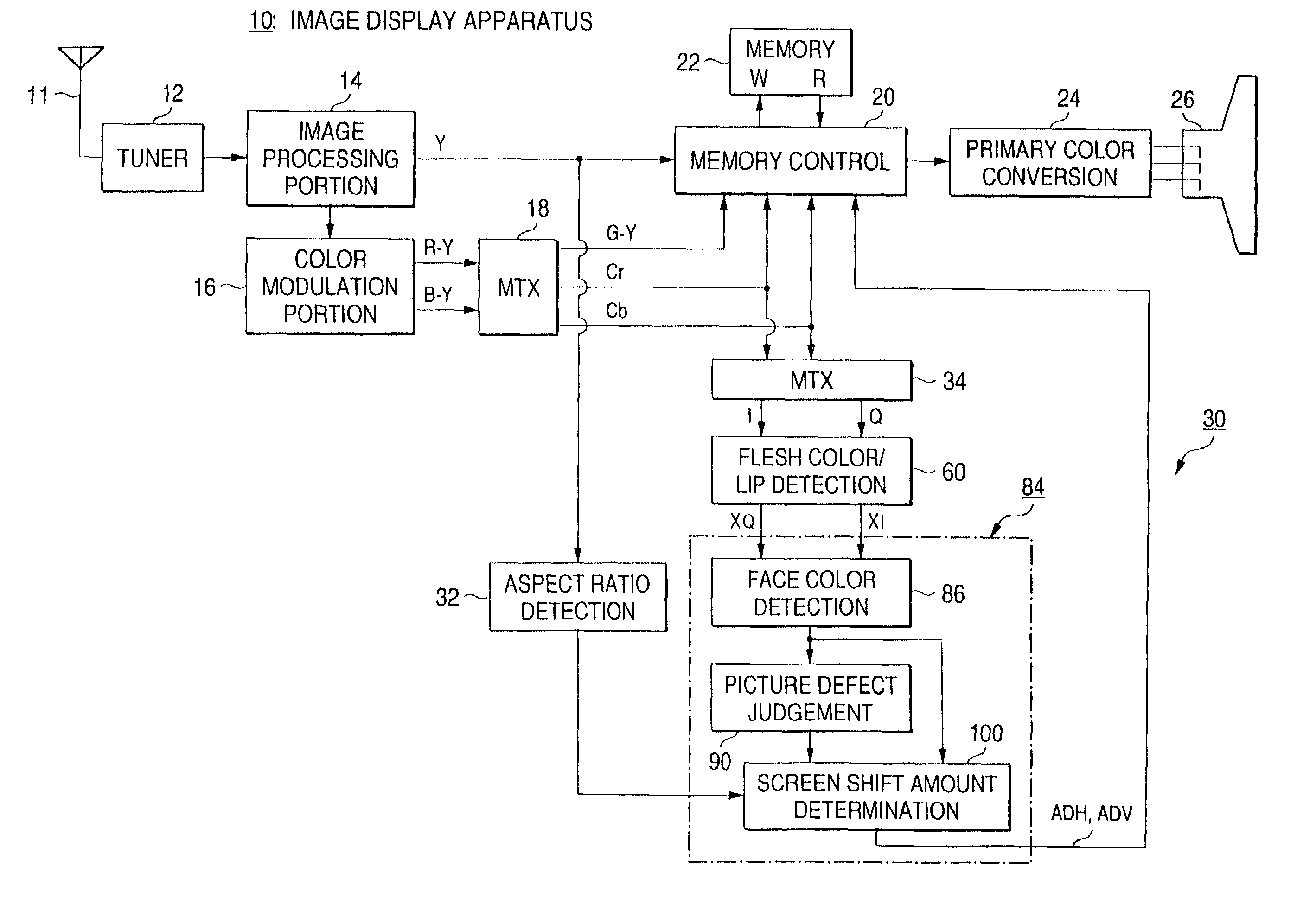
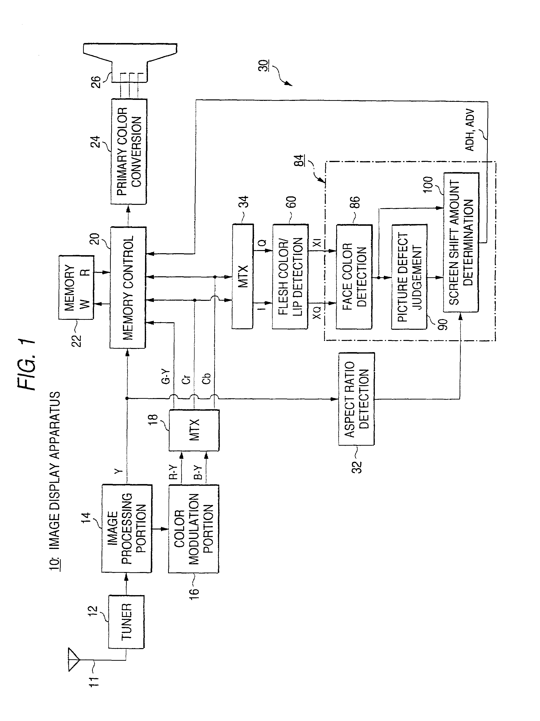
[0044]An embodiment of an image display apparatus of the present invention will be described in detail with reference to FIG. 1 and the following.

[0045]In an image display apparatus 10 shown in FIG. 1, an input image signal received by an antenna 11 is tuned by a tuner 12, and the tuned input image signal is supplied to an image processing portion 14 and a luminance signal Y is demodulated. A carrier chrominance signal extracted by the image processing portion 14 is supplied to a color demodulation portion 16, and a pair of color difference signals (R-Y) and (B-Y) are demodulated, and the demodulated color difference signals are supplied to a matrix circuit 18, so that a color difference signal (G-Y) and a pair of chrominance signals Cr and Cb are generated in this example.

[0046]On the other hand, the luminance signal Y outputted from the image processing portion 14 is written in a memory means 22 through a memory control portion 20. The color difference signal (G-Y) and the pair of...


PUM


Abstract

There is provided an image display apparatus which automatically detects a picture defect and shifts an image region to eliminate the picture defect. The image display apparatus includes a memory unit for temporarily storing an input image signal, a memory control unit for controlling a readout start address for the memory unit, a display unit to which the image signal read out of the memory unit is supplied, a detection unit of an aspect ratio of the input image signal, and an address control signal generation unit to which an aspect ratio detection output is supplied from the detection unit and which generates a readout start address control signal for the memory unit from the input image signal. When the input image signal having an aspect ratio different from an aspect ratio of image screen display of the display unit is supplied, a readout start address is controlled on the basis of the address control signal generated by the address control signal generation unit. By this, an image region is automatically shifted and a picture defect is prevented without changing the aspect ratio of the input image signal when an object is a human figure.

Description

BACKGROUND OF THE INVENTION[0001]1. Field of the Invention[0002]The present invention relates to an image display apparatus capable of correcting a picture defect of a human figure or the like, and more particularly to an image display apparatus in which when an aspect ratio of a screen is different from an aspect ratio of an input image signal, even in the case where an input image is displayed without changing the aspect ratio of the input image signal, a picture defect of a human figure or the like can be automatically corrected.[0003]2. Description of the Related Art[0004]When an image of an input image signal is displayed on a display means having an aspect ratio different from an aspect ratio of the image, in the case where the image is displayed while the aspect ratio of the input image signal is kept, the following image modes are conceivable.[0005]FIG. 14A shows a state in which a display means has an aspect ratio of (4:3) and an input image signal of (16:9) is displayed on...

Claims


Application Information

Patent Timeline
Patent Type & Authority Patents(United States)
IPC IPC(8): H04N11/20H04N7/01H04N3/27H04N5/46H04N7/015
CPCH04N7/0122
Inventor TAKECHI, AYAKOJIMA, HIROYUKIUEKI, NOBUO
Owner SONY CORP
Learn More