Back-porch clamp

a back-porch and clamping technology, applied in the field of video signal processing, can solve the problems of inability to accurately time the bpc pulse, the location of horizontal sync is not known, and the vdec b>14 is difficult to achiev

Inactive Publication Date: 2006-10-24
THOMSON LICENSING SA
View PDF11 Cites 10 Cited by
  • Summary
  • Abstract
  • Description
  • Claims
  • Application Information

AI Technical Summary

Benefits of technology

[0012]The characteristics and advantages of the present invention will become more apparent from the following description, given by way of example.

Problems solved by technology

However, when video is first applied to the A / D Converter 12 input, the bias voltage of the VDEC 14 input will likely be outside the dynamic range of the VDEC 14 and will thus make it difficult for the VDEC 14 to determine the location of horizontal sync and thus a properly timed BPC pulse will not be available.
There are several problems encountered when implementing a back-porch clamp as described above.
Third, the loop response stability is difficult to achieve as two dominant poles, associated with input capacitor 8 and filter capacitor 34, are employed, and initial stabilization of the loop is lengthy due to the difficulty of identifying the back-porch interval when the A / D Converter 12 and VDEC 14 are initially outside their optimal dynamic range.

Method used


Image

  • Back-porch clamp
  • Back-porch clamp
  • Back-porch clamp

Examples


Embodiment Construction

[0012]The characteristics and advantages of the present invention will become more apparent from the following description, given by way of example.

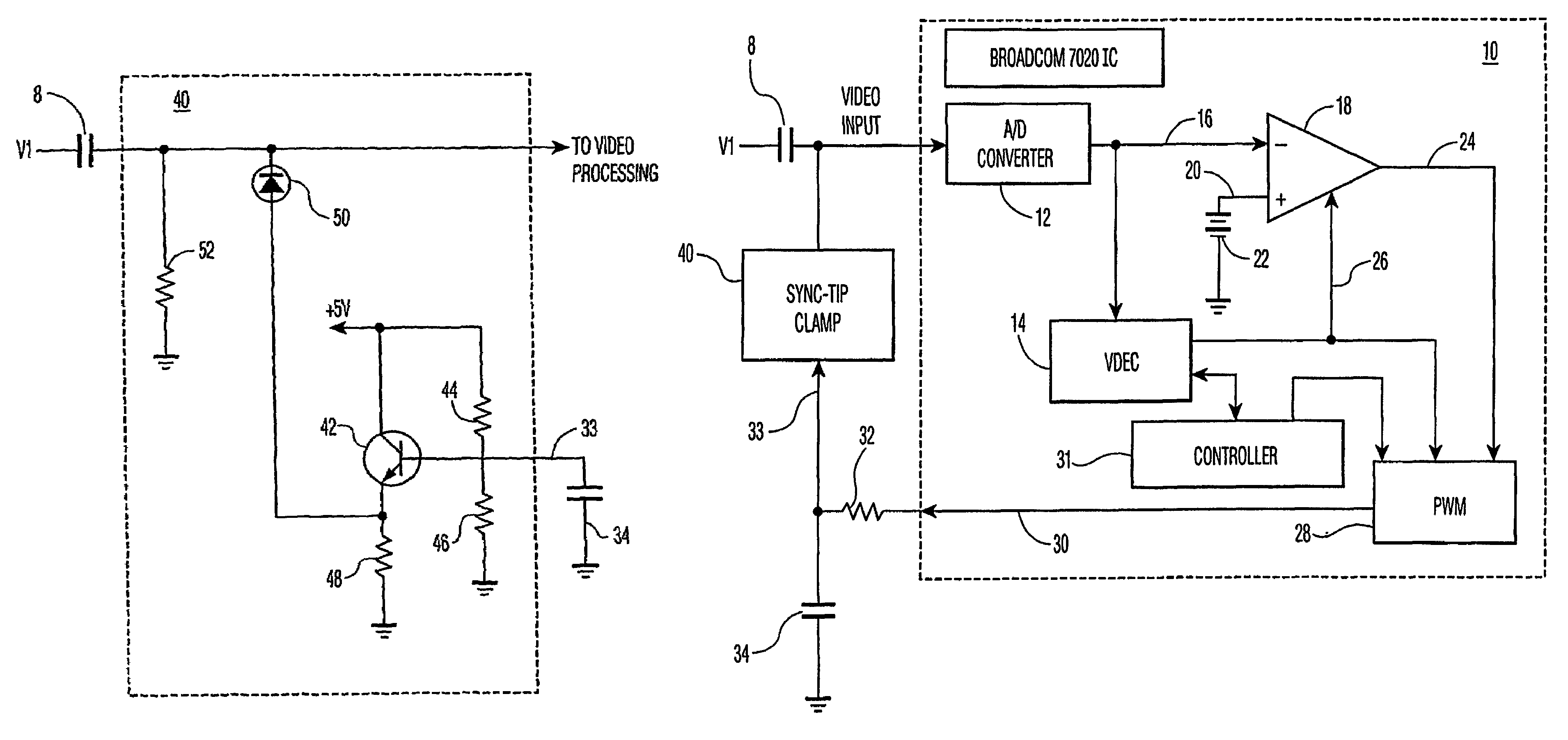
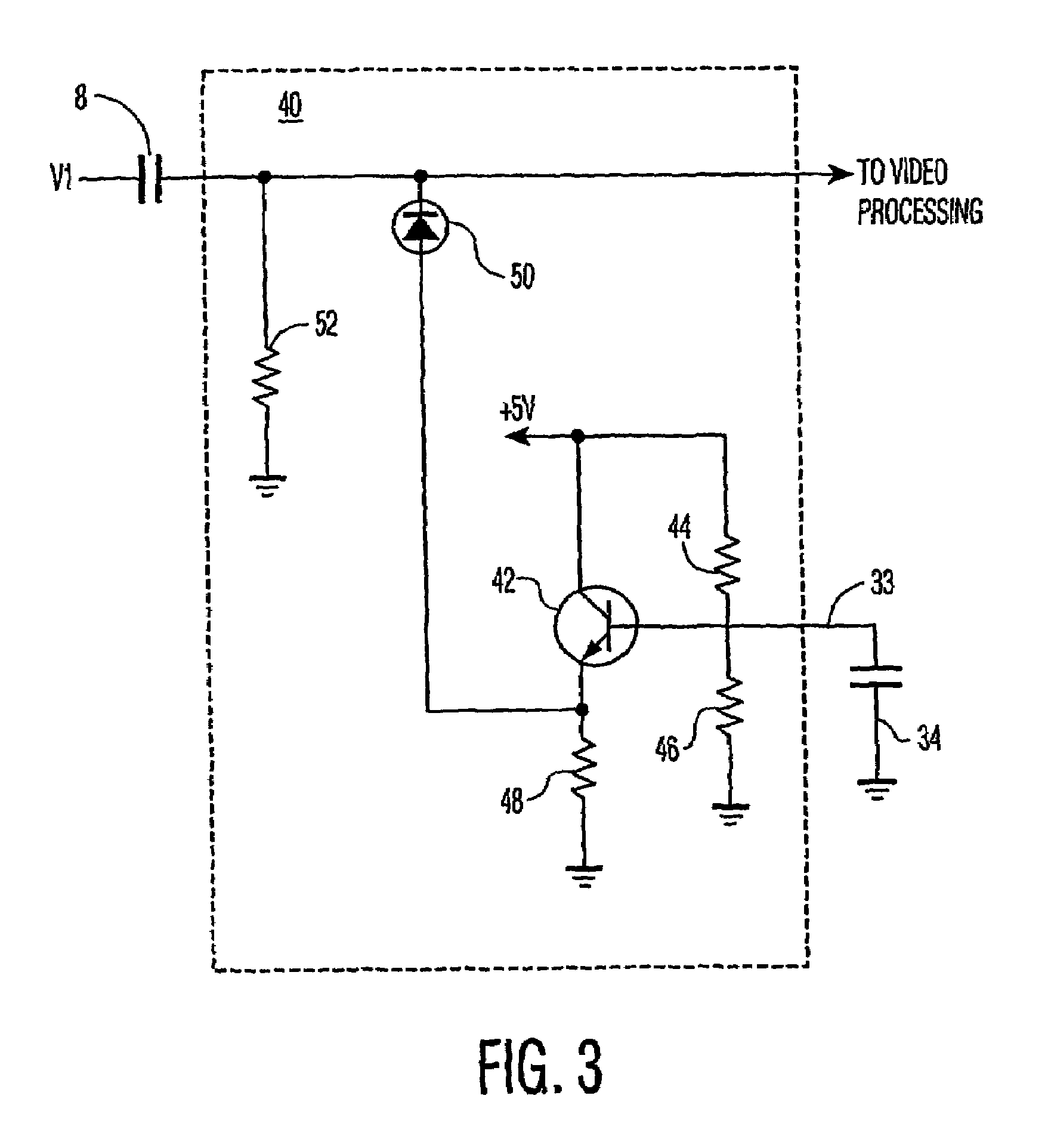
[0013]Referring to FIG. 3, an exemplary sync-tip clamp 40 used in conjunction with a video input to a video processing unit such as a Broadcom 7020 IC is shown. A transistor 42, circuitry on the base of the transistor, (i.e., a resistor 44, a resistor 46 and a capacitor 34), and an emitter resistor 48 provide a solid DC voltage. The clamp action Is performed by a diode 50, a leak resistor 52, and a coupling capacitor 8. The voltage to which the sync-tip will be clamped is determined by the divider ratio of resistors 44 and 46.

[0014]Referring now to FIG. 4, when PWM signal 30 is applied to the sync-tip clamp reference input 33 through resistor 32, the PWM output 30 will be low-pass filtered by capacitor 34 and will provide a variable reference to the sync-tip clamp. In this way the sync-tip level and thus the back-porch level of the video...


PUM


Abstract

The invention teaches a method, means and apparatus for clamping a back porch interval of a video signal including clamping a sync-tip level of said video signal to a variable reference voltage, comparing a back-porch voltage level of the sync-tip clamped video signal to a predetermined reference voltage, generating an error signal representative of the difference between the back-porch voltage level and the predetermined reference voltage, and adjusting the variable reference voltage in response to the error signal such that the error signal is minimized.

Description

[0001]This application claims the benefit, under 35 U.S.C. §365 of International Application PCT / US01 / 43145, filed Nov. 21, 2001, which was published in accordance with PCT Article 21(2) on May 30, 2002 in English and which claims the benefit of U.S. patent application No. 60 / 253,190, filed Nov. 27, 2000.FIELD OF THE INVENTION[0002]The present invention relates to video signal processing.BACKGROUND OF THE INVENTION[0003]In video signal processing systems, either purely analog or digitized video, it is often desirable to implement a back-porch clamp to set the DC operating point of the signal to a predetermined reference voltage. To understand conventional practice, the recommended operation of the Broadcom 7020 IC 10 as shown in FIG. 1 is explained. A video signal V1 is buffered by a Video Op Amp 6 and is provided through a coupling capacitor 8 to the Video Input of IC 10 wherein it is digitized by an A / D Converter 12 and applied, in parallel, to a Video Decoder (VDEC) 14 and one in...

Claims


Application Information

Patent Timeline
IPC IPC(8): H04N5/16H03M1/12H04N5/18
CPCH03M1/1295H04N5/18H04N5/185
Inventor KEEN, RONALD THOMAS
Owner THOMSON LICENSING SA
Why Eureka
Try Eureka