Locking device for heat dissipating device

a technology of locking device and heat sink, which is applied in the direction of snap fasteners, light and heating apparatus, buckles, etc., can solve the problems of difficult detachment of push-in pins, inability of heat sink b>200/b> to intimately contact with the cpu, and inability to detach push-in pins. , to achieve the effect of convenient detachment of heat sink from electronic components

Inactive Publication Date: 2006-10-24
HON HAI PRECISION IND CO LTD
View PDF13 Cites 74 Cited by
  • Summary
  • Abstract
  • Description
  • Claims
  • Application Information

AI Technical Summary

Benefits of technology

[0005]Accordingly, an object of the present invention is to provide a locking device which can firmly mount a heat sink to an electronic component for a long term and conveniently detach the heat sink from the electronic component.

Problems solved by technology

However, it is difficult to detach the push-in pins 300 from the printed circuit board 500 in disassembly.
Furthermore, the springs 400 are prone to fatigue after a long time using.
As a result, the heat sink 200 is not capable of intimately contacting with the CPU 600 in an acceptably long-used period.

Method used


Image

  • Locking device for heat dissipating device
  • Locking device for heat dissipating device
  • Locking device for heat dissipating device

Examples


Embodiment Construction

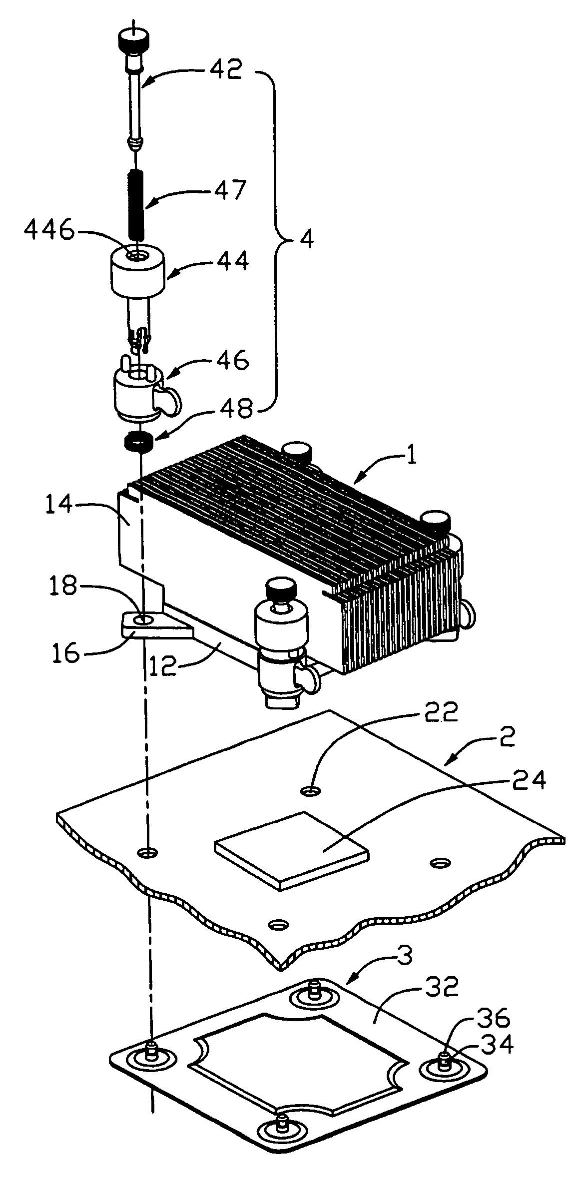
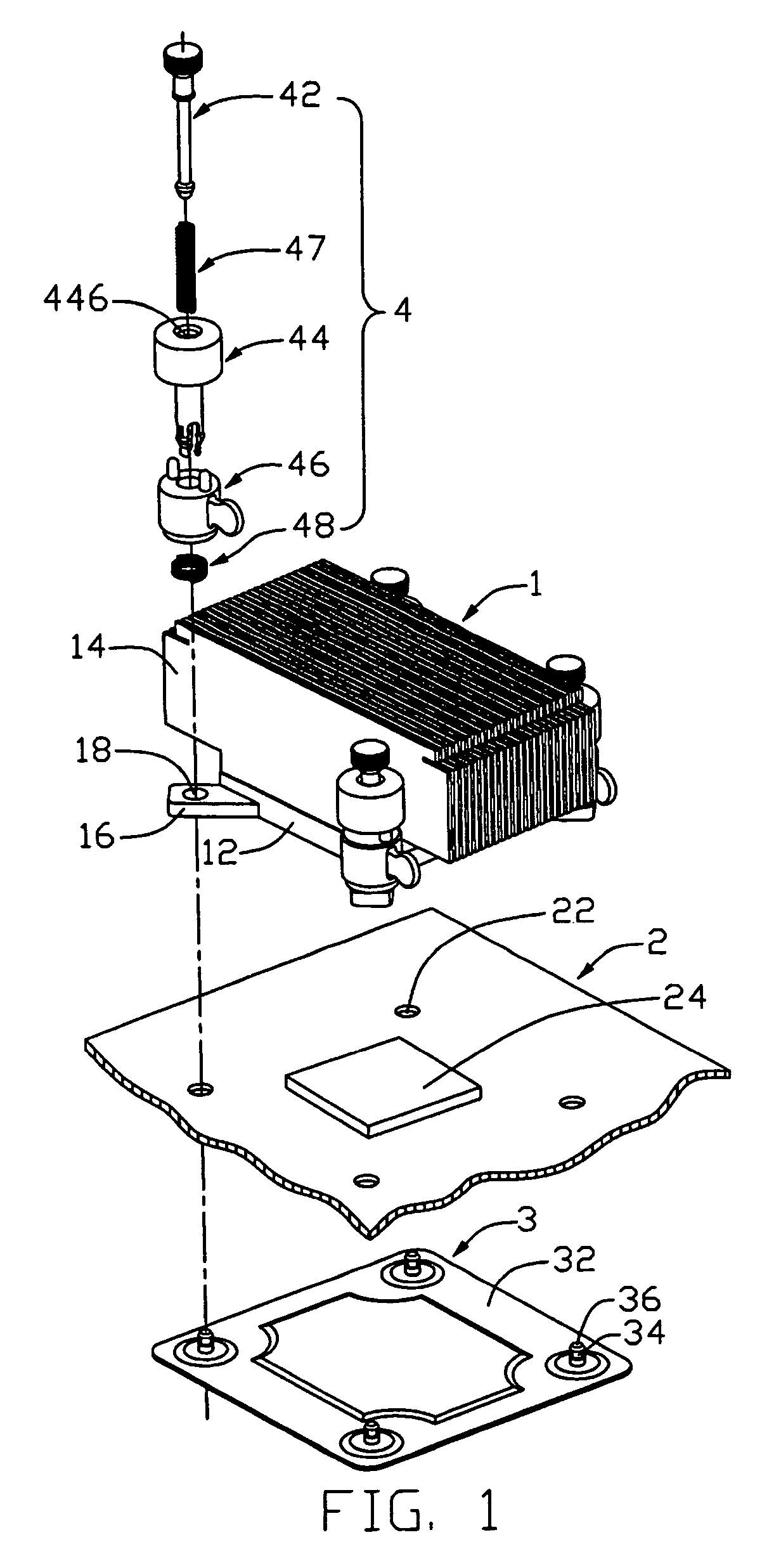
[0013]FIG. 1 shows a locking device in accordance with a preferred embodiment of the present invention for mounting a heat sink 1 to a printed circuit board 2. The printed circuit board 2 defines four through holes 22. An electronic component 24, such as a central processing unit (CPU), is installed on the printed circuit board 2, surrounded by the through holes 22. The heat sink 1 comprises a base 12 for contacting the CPU 70 and a plurality of fins 14 extending from the base 12. Four extension arms 16 extend from four corners of the base 12. Each arm 16 defines a through hole 18 corresponding to one of the through holes 22 of the printed circuit board 2.

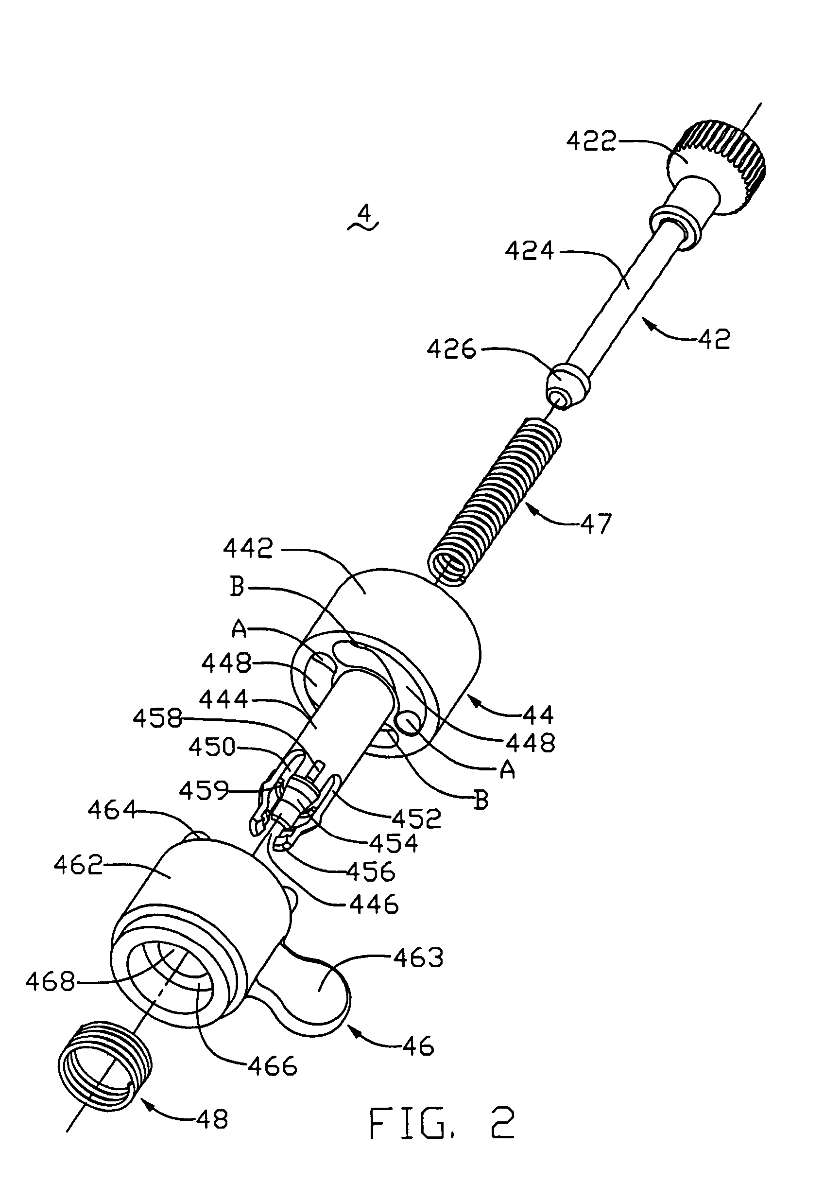
[0014]The locking device comprises a back plate 3 and four retainers 4. The back plate 3 is for being mounted below the printed circuit board 2 and comprises a body 32 and four posts 34 extending upwardly from corners of the body 32. Each post 34 forms a barb 36 on a top end thereof to form a fastener. Each retainer 4 comprises a p...


PUM


Abstract

A locking device for mounting a heat sink to a CPU mounted on a printed circuit board, includes a back plate mounted below the circuit board and having a plurality of fasteners extending upwardly beyond the circuit board, and a plurality of retainers. Each retainer includes an operating member resting on a heat sink, a locking member extending through the operating member, and a pushing member extending through the locking member. The locking member includes a locking structure extending through the heat sink to engage with one of the fasteners. The pushing member includes a taper bottom portion. The pushing member is downward movable to cause the taper bottom portion to disengage the locking structure from the one of the fasteners.

Description

TECHNICAL FIELD[0001]The present invention relates to a locking device, and particularly to a locking device which can conveniently mount a heat sink to an electronic component.BACKGROUND[0002]As computer technology continues to advance, electronic components such as central processing units (CPUs) of computers are made to provide faster operational speed and greater functional capabilities. When a CPU operates at a high speed in a computer enclosure, its temperature increases greatly and dramatically. It is desirable to dissipate the generated heat quickly, for example, by using a heat sink attached to the CPU in the enclosure. This allows the CPU and other electronic components in the enclosure to function within their normal operating temperature ranges, thereby assuring the quality of data management, storage and transfer. Generally, a locking device is required for mounting the heat sink to the CPU.[0003]FIG. 5 shows a conventional locking device for mounting a heat sink 200 to...

Claims


Application Information

Patent Timeline
Patent Type & Authority Patents(United States)
IPC IPC(8): H05K7/20H01L23/34H01L23/40
CPCH01L23/4093H01L2924/0002Y10T24/42H01L2924/00
Inventor CHEN, CHUN-CHIZHOU, SHI-WENLEE, HSIEH-KUN
Owner HON HAI PRECISION IND CO LTD
Why Eureka
Try Eureka