Device and method for margin marking tissue to be radiographed

a technology for radiography and tissue, applied in the field of devices for marking specimens, can solve the problems of frustration between three professionals, unsatisfactory marking of specimens removed from patients, and inability to perform suturing and knotting regularly, so as to reduce confusion, reduce the amount of obstruction, and be easily gripped

Inactive Publication Date: 2006-10-24
BEEKLEY A CT
View PDF5 Cites 97 Cited by
  • Summary
  • Abstract
  • Description
  • Claims
  • Application Information

AI Technical Summary

Benefits of technology

[0010]One advantage of the present invention is that the device may standardize the marking system used to indicate the orientations of the marked tissue, thereby eliminating confusion between the different medical professionals involved in treatment. Another advantage is that the device may remain fixedly secured to the tissue during radiography because the device can be attached to the tissue with a suture, staple, or like connecting means, rather than relying on any pinching or squeezing elements that can accidentally release. Still another advantage is that the base of the device itself may be configured to be easily gripped during use, even though the markers themselves may be relatively small (so as to limit the amount of obstruction during xray). Yet another advantage is that the device may be able to retain multiple markers with various indicia, wherein one or more of the markers may be usable for the same or multiple sections of tissue. Additionally, the device may be readily adaptable to mark all types of tissue and orientations.

Problems solved by technology

All of the previously described devices, while useful for specific purposes, have not been ideal for marking specimens removed from patients, as the described devices fail to address circumstances particular to specimen removal, radiography, and pathology.
Unfortunately, this process of suturing and knotting may not be regularly performed because it is time consuming and requires detailed oral and / or written communications between surgeons, radiologists, and pathologists which can result in frustrations between the three professionals.
Additional confusion may arise due to the fact that there is no standard marking method in the medical profession, since each surgeon develops his or her own method of marking.
For example, existing markers can be attached to specimens by securing the markers with a clamping pair of pinchers, but these markers may release while the specimen is being radiographed and otherwise examined, and thus, the benefit is lost.
Also, because such existing markers have sliding components and locking points, they tend to be thicker and larger than ideal.
While the simple solution to this problem would be to decrease the marker size, if the marker is too small, it may be virtually impossible to hold while securing to a specimen.
Existing devices also fail to standardize the method of marking specimens, thereby perpetuating the confusion and misinterpretation between the surgeon removing the specimen and the pathologist studying the specimen.

Method used


Image

  • Device and method for margin marking tissue to be radiographed
  • Device and method for margin marking tissue to be radiographed
  • Device and method for margin marking tissue to be radiographed

Examples


Embodiment Construction

[0019]The present invention overcomes many of the problems that arise when other radiopaque markers are used to mark radiography specimens. The advantages, and other features of the disclosed device, will become more readily apparent to those having ordinary skill in the pertinent art from the following detailed description of certain preferred embodiments taken in conjunction with the drawings which set forth representative embodiments of the present invention and wherein like reference numerals identify similar structural elements.

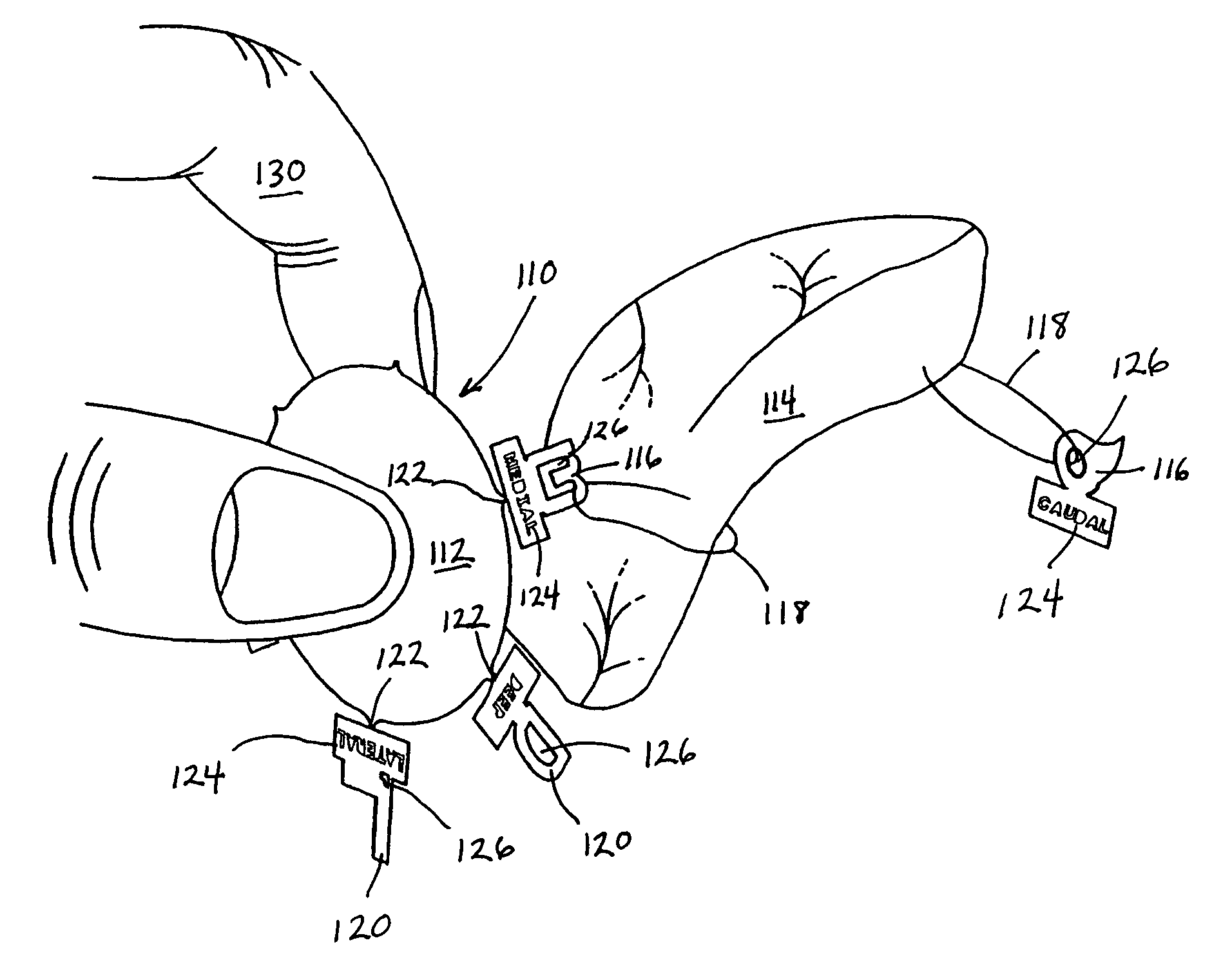
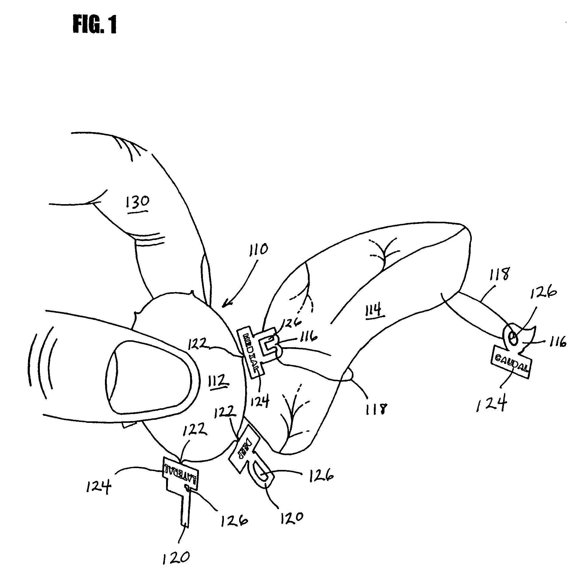
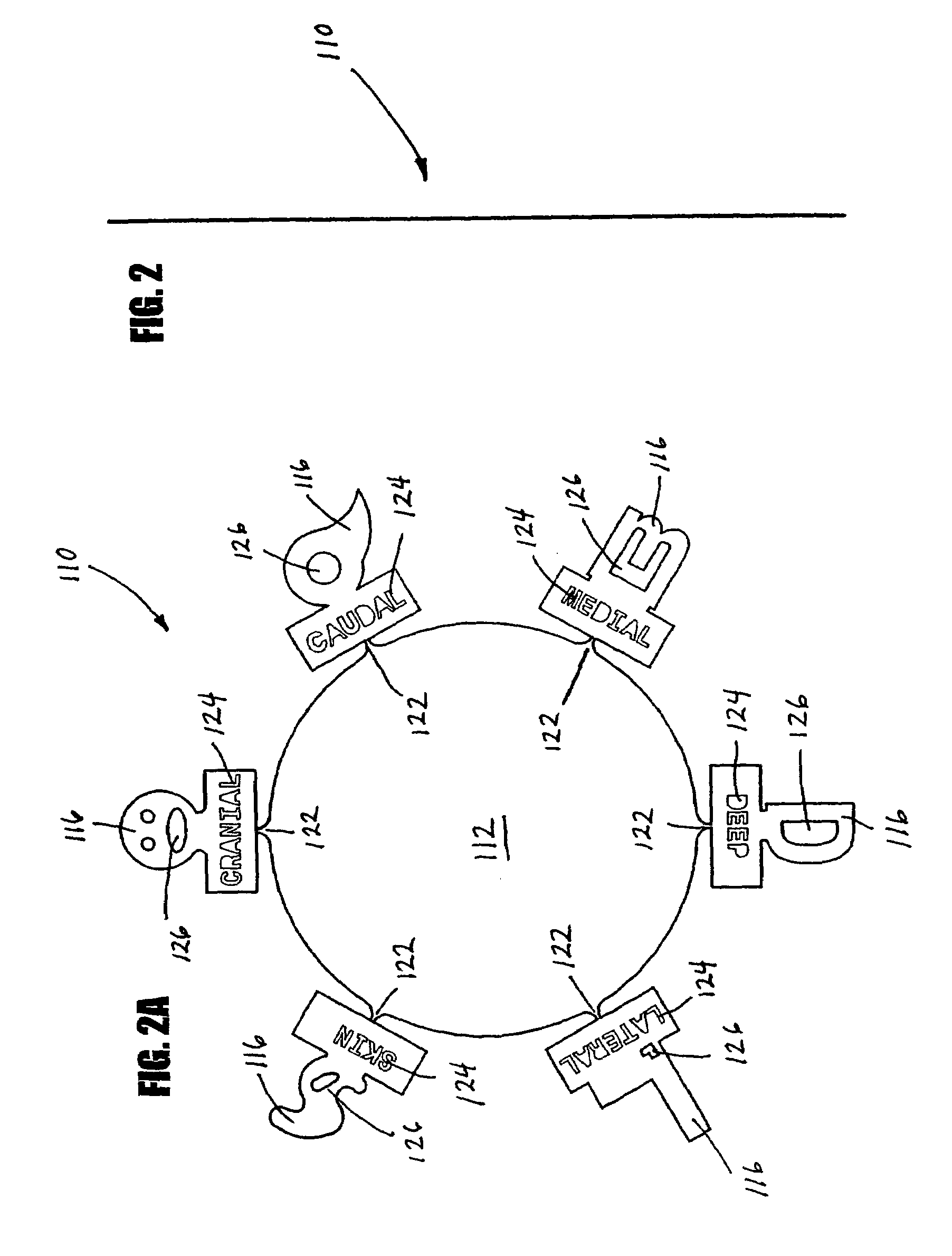
[0020]In FIGS. 1, 2, and 2A–C, numeral 110 generally refers to a margin marking device. In FIG. 1, a marker 116 is being secured to a specimen 114 to mark the margins of the specimen. The marker 116 defines an aperture 126 sized to accommodate sutures 118, staples, or like connecting means for securing the marker 116 to the specimen 114. The sutures 118 may be any length, although longer lengths will allow the marker 116 to be moved away from the specime...


PUM


Abstract

A marking device for defining the margins and orientation of radiography specimens includes a plurality of visually distinctive markers joined by a base that holds the markers until the markers are secured to a specimen. The base serves as a holder for the individual markers as the markers are secured to a specimen with sutures or staples, at which time the markers are disconnected from the base. One or more markers may be secured to a specimen as needed to define the orientation of the specimen. By securing markers to specific locations on a specimen, a surgeon can indicate to radiologists and pathologists the specimen's orientation in the body before removal, thus aiding in future study of the specimen. Since the markers are made either wholly or partially from radiopaque material, the markers are visible when radiographed.

Description

CROSS-REFERENCE TO RELATED APPLICATIONS[0001]This application is a continuation of U.S. patent application Ser. No. 10 / 243,352, filed Sep. 13, 2002, now U.S. Pat. No. 6,826,257, titled “Device and Method for Margin Marking of Radiography Specimens”, which is hereby incorporated by reference in its entirety.FIELD OF THE INVENTION[0002]The present invention relates to devices for marking radiography specimens, and in particular to devices that indicate the orientation of the specimen in a patient's body prior to removal. The present invention further relates to radiographic markers that will remain secured to specimens during manipulations accompanying radiography and pathology.BACKGROUND INFORMATION[0003]Radiologists frequently use markers that absorb xrays and cast an image when placed within an xray field to convey pertinent information on xray film. For example, right and left markers are routinely used to designate the anatomical orientation of the patient or to identify a partic...

Claims


Application Information

Patent Timeline
Patent Type & Authority Patents(United States)
IPC IPC(8): H05G1/28A61B10/00A61B10/02A61B19/00
CPCA61B19/54A61B10/02A61B2019/5408A61B2019/5437A61B90/39A61B2090/3908A61B2090/3937
Inventor SAYRE, JAMESBOBER, STEWART
Owner BEEKLEY A CT
Why Eureka
Try Eureka