Image processing method and image processing apparatus

a technology of image processing and illumination level, applied in the field of image processing method and image processing apparatus, can solve the problems of subjective undesirable noise, insufficient prevention of problems, and decline of contrast in other level ranges, so as to reduce the influence of illumination level on a change in pixel value, appropriately extract the

Active Publication Date: 2006-10-24
SONY CORP
View PDF6 Cites 52 Cited by
  • Summary
  • Abstract
  • Description
  • Claims
  • Application Information

AI Technical Summary

Benefits of technology

[0016]In the invention, for example, the threshold of the epsilon filter is controlled so that the larger the edge strength is, the smaller a value of the threshold becomes. In this case, the threshold of the epsilon filter may be further controlled so that the larger a pixel value of the input image is, the larger the threshold becomes. Thereby, in filtering by the epsilon filter, an influence of an illumination level on a change in the pixel value can be reduced, so an illumination component can be appropri

Problems solved by technology

Therefore, there is a problem that when a contrast in any level range (the gradient of the level conversion function) is increased, conversely, contrasts in other level ranges declines.
However, there is a problem that when an illumination condition is suddenly switched, the linear filter cannot extract a change in the illumination condition, so a subjectively undesirable noise occurs.
In the Multiscale retinex method, in order to overcome the problem, a method of using a plurality of linear lowpass filters with different scales, and

Method used


Image

  • Image processing method and image processing apparatus
  • Image processing method and image processing apparatus
  • Image processing method and image processing apparatus

Examples


first embodiment

[First Embodiment]

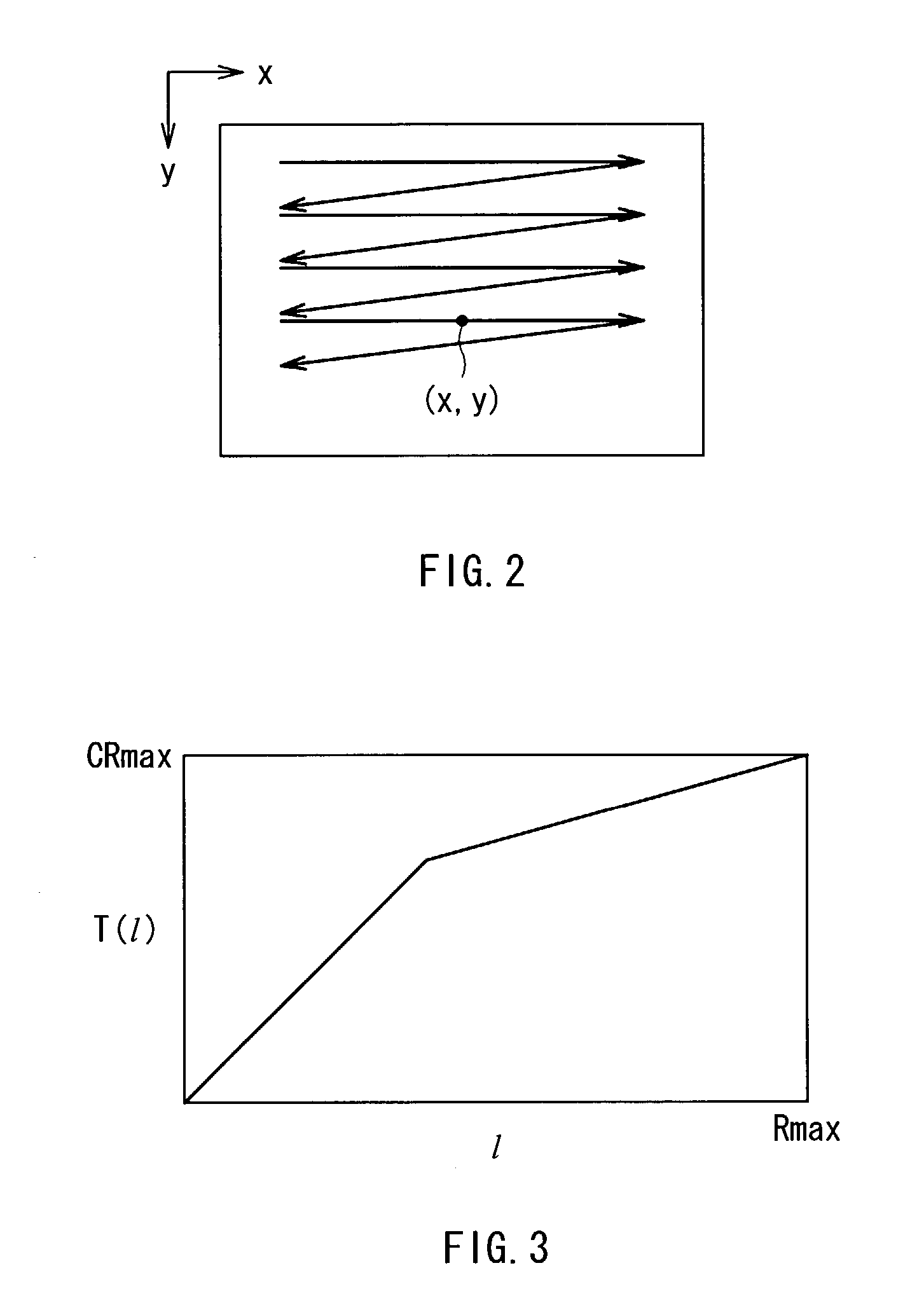
[0040]At first, an input image signal which is processed in an image processing apparatus according to a first embodiment of the invention will be described below. The input image signal processed in the image processing apparatus is a signal of a time-series pixel value obtained by scanning a two-dimensional digital image in a horizontal direction and a vertical direction in this order as shown in FIG. 2. In the embodiment, the pixel value corresponding to any position (x, y) on the two-dimensional image indicates I(x, y), and the pixel value is processed as an input image signal.

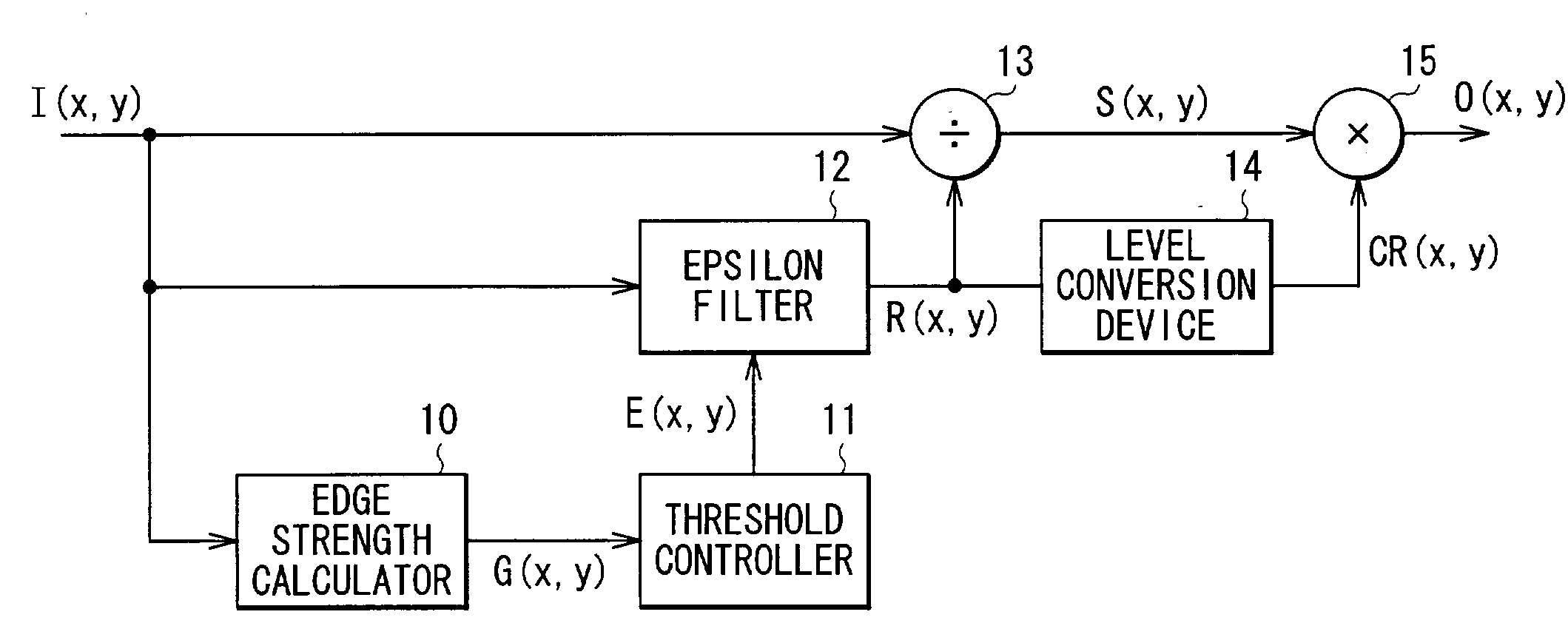
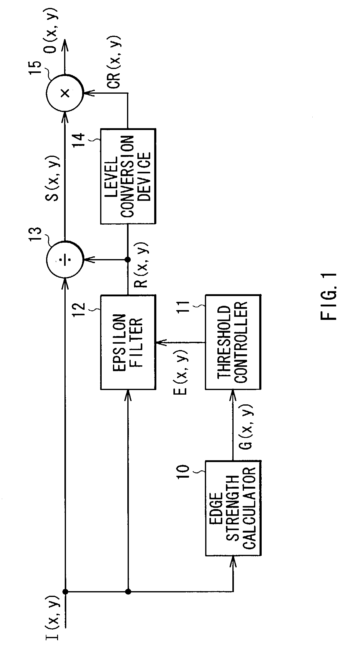
[0041]Next, a structure of the image processing apparatus according to the embodiment will be described below. As shown in FIG. 1, the image processing apparatus comprises an edge strength calculator 10, a threshold controller 11, an epsilon filter 12, a divider 13, a level conversion device 14 and a multiplier 15.

[0042]The edge strength calculator 10 has a function of calculating an edge...

second embodiment

[Second Embodiment]

[0111]Next, a second embodiment of the invention will be described below. In the description below, like components are denoted by like numerals as of the first embodiment and will not be further explained.

[0112]FIG. 12 shows a structure of an image processing apparatus according to the second embodiment of the invention. Although a general function of the image processing apparatus according to the embodiment is the same as that according to the first embodiment, it is distinguished from the first embodiment by the fact that in the embodiment, instead of the divider 13 and the level conversion device 14 (refer to FIG. 1), the image processing apparatus comprises a coefficient calculator 16 having functions of the divider 13 and the level conversion device 14. In other words, in the embodiment, the dynamic range is compressed on the basis of Mathematical Formula 16 described in the first embodiment.

[0113]In the embodiment, the coefficient calculator 16 calculates ...

third embodiment

[Third Embodiment]

[0116]Next, a third embodiment of the invention will be described below. In the description below, like components are denoted by like numerals as of the first embodiment and the second embodiment and will not be further explained.

[0117]FIG. 14 shows a structure of an image processing apparatus according to the third embodiment of the invention. Although the structure of the image processing apparatus according to the embodiment is substantially the same as that according to the first embodiment (refer to FIG. 1), it is distinguished from the first embodiment by the fact that in addition to the edge strength G(x, y) which is the output from the edge strength calculator 10, the pixel value I(x, y) of the input image is directly inputted into the threshold controller 11.

[0118]In the embodiment, a threshold controller 11A controls the threshold E(x, y) used in the epsilon filter 12 in a subsequent stage by not only the edge strength G(x, y) but also the pixel level of...


PUM


Abstract

By the use of an epsilon filter, in the case where a plurality of different illuminations exist, a boundary between the illuminations can be appropriately extracted, and an unnatural image pattern can be prevented from being generated, therefore subjectively preferable compression of a dynamic range can be achieved. An edge strength G(x, y) is calculated per position on an input image, and a threshold E(x, y) of an epsilon filter (12) is controlled on the basis of the edge strength G(x, y). The epsilon filter (12) filters the input image on the basis of the controlled threshold E(x, y). On the basis of the edge strength G(x, y), the threshold E of the epsilon filter (12) is adaptively changed according to a local gradient of a pixel value I(x, y), so in the case of using a linear lowpass filter or a fixed threshold epsilon filter, an illumination boundary can be more accurately extracted.

Description

TECHNICAL FIELD[0001]The present invention relates to an image processing method and an image processing apparatus suitably applicable to various image input / output devices such as televisions, video tape recorders, still cameras, video cameras and printers, and more specifically to an image processing method and an image processing apparatus for reproducing an inputted image in an imaging device with a relatively narrow dynamic range.BACKGROUND ART[0002]As a conventional method, there is a method (hereinafter referred to as “level conversion”) of converting each pixel of an input image by a function having an input / output relationship (hereinafter referred to as “level conversion function”) indicated by a solid line in FIG. 18, for example, for conversion of gradation characteristics of an image. In FIG. 18, a lateral axis indicates a pixel level (input level) l of an input image, and a vertical axis indicates a pixel level (output level) T(l) of an output image by the level conver...

Claims


Application Information

Patent Timeline
IPC IPC(8): G06K9/40G06T5/00G06T5/20H04N1/407H04N5/20
CPCG06T5/002G06T5/20G06T7/0083G06T2207/10016G06T2207/20012G06T2207/20192G06T7/12H04N5/208
Inventor OGATA, MASAMIUEDA, KAZUHIKO
Owner SONY CORP
Why Eureka
Try Eureka